In this article explained about basic concepts in carbonation process for sugar refining like Reactions and Process Description, Flow diagram of carbonation Process, Main Equipment Operation and Specifications, CO2 Gas scrubbing system and Filtration process of carbonated liquor.
Sugar Refinery Carbonation Process | Sugarprocesstech
Objective of Carbonation Process
a) The objective of these processes is to remove the impurities that cause turbidity in raw melt liquor.
b) Carbonation is generally applied to melt liquor in the refinery ahead of any decolourising process.
c) Carbonation has a good effect on sugar liquors. It is also purification process, enabling a colour reduction of about 40% to 50% together with a reduction in ash content of about 20-25%.
d) The addition of lime and Carbon Dioxide in the sugar liquor produces Calcium Carbonate precipitates that adsorb the impurities and coloring matter present in the sugar liquor. Less soluble salts such as sulphates, colour bodies, starch, and many other impurities are entrapped by the calcium carbonate.
e) These impurities are subsequently removed in the succeeding filtration process.
Reactions in Carbonation process
a) This carbonation process involves two distinct steps.
b) The first step involves the formation of a voluminous and gelatinous precipitate by reaction of calcium and CO2.
c) The second step involves the conditioning of the precipitate in order to improve its filterability.
Ca (OH)2 + CO2 = CaCO3 + H2O
d) The impurities are both absorbed by, and enmeshed in, the conglomerated particles of the calcium carbonate precipitated by the reaction of the carbon dioxide and calcium hydroxide.
e) This calcium carbonate entraps wax, gums, polysaccharides, colorants and ash and also destroys the invert sugars. This precipitate that contains most of the impurities from the sugar solution is removed in the process in the succeeding filtration processes.
Carbonation Process Description
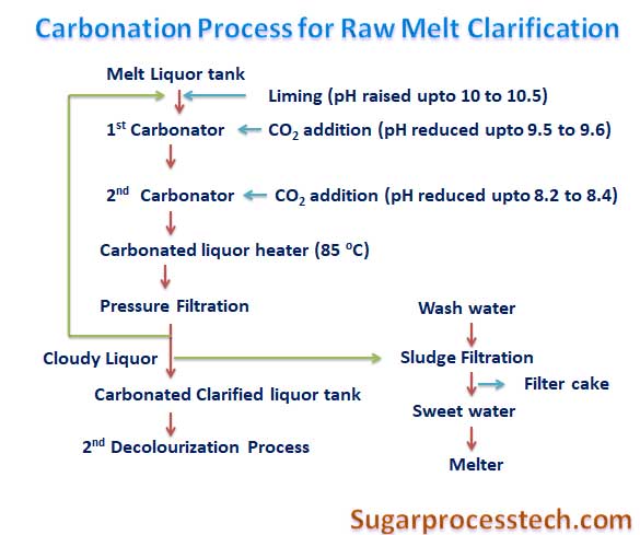
a) The process consists of adding slurry of calcium hydroxide into the raw melt solution in liming tank to increase the pH to 10.5 – 11.
b) Liming tank is equipped with agitator to keep the liquor and lime solution mixture in suspension and for better mixing.
c) Generally the carbonation process consists of two no’s of carbonators working in series as 1st carbonator and 2nd
d) The limed liquor from the liming tank flows transfer to first carbonator tank where scrubbed Carbon Dioxide gas drawn from Boiler flue gas after dilution is admitted to react with lime in the limed liquor to form calcium carbonate.
e) The CO2 addition will be controlled according to the carbonated liquor pH.
f) In 1st carbonated liquor tank pH maintained about 9.5 – 9.6 and amount of 75 -85 % of carbon dioxide gassing is carried out in the first carbonator tank.
g) The carbonated liquor passing from 1st carbonator to second carbonator. The pH of 2nd carbonated liquor tank comes is 8.2-8.4 and amount of 15 – 25 % of carbon dioxide gassing is carried out in the second carbonator tank.
h) Carbonated liquor from the second carbonator tanks flows by gravity into carbonated liquor buffer tank.
i) Each carbonator is equipped with Richard tubes for better mixing of CO2 with the liquor and facilitates the on line cleaning of nozzles and avoids jamming, which results better colour reduction in the carbonation system.
j) Boiler flue gas is used as source of CO2 requirement for this carbonation process and the concentration CO2 gas is about 12-14% in scrubbed flue gases.
k) The carbonated liquor heated to 850C in tubular heaters and filtered in Membrane pressure filters to separate the calcium carbonated precipitate from liquor.
l) Clarified melt from the carbonation system will be subjected to 2nd decolonization process.
Flow diagram of carbonation Process in Sugar Refinery for raw melt clarification.
Main/Ancillary Equipment Operation and Specification for Carbonation process
1. Liming Tank
a) Liming tank with stirrer and located adjacent to the top of the 1st carbonators are provided to ensure more uniform and thorough mixing of raw liquor and milk of lime.
b) The amount of milk of lime added to the raw liquor is controlled by adding proportionate volume of milk of lime in relation to flow of raw liquor going to liming tank.
c) The ratio of raw liquor and milk of lime can be adjusted to obtain the desired pH.
d) pH sensor is also installed on the limed liquor sampling box to measure the actual pH of the lime liquor leaving the Liming tank.
e) Lime consumption/ton of sugar will be maximum 7 to 10 kg or the amount of lime used is on the order of 0.5 to 0.8% CaO on melt.
f) Milk of lime is generally prepared at a concentration of about 10 to 15o
2. First and Second Carbonation Tanks
a) Carbonator is also called saturator or reactor
b) Total liquid volume contained in the both saturators is generally sized to give an overall residence time of liquor in the system of about 1 hour.
c) Longer residence times in reactor generally give higher color removal and better maturity level of precipitate for filterability, but above 1 hour the benefit is much reduced, and losses of reducing sugars are increased.
d) Normal liquor retention time of 30-40 minutes will be maintained in each carbonation tanks depend upon the requirement.
e) Liquid height in the saturator vessel is normally limited according to head the CO2 gas pumps. Generally limited to about 2.5 m.
f) The gas distribution system shall be distribute the gas uniformly over the cross-sectional area of the saturator, produce a large number of small bubbles and ensure sufficient agitation in the vessel.
g) The right degree of mixing is obtained with superficial gas velocities in the range 10 to 15 which should be considered in assessing the geometry of the saturator vessels.
3. CO2 Gas production
a) Boilers flue gas is one of the major sources for gas production for this process.
b) The content CO2 % in flue gas depends fuel being fired in the boilers
i) Coal firing boilers having around 10 to 12%
ii) Bagasse firing boilers having around 12 to 14%
iii) Gas firing boilers having around 7 to 8%
c) Generally, two-stage scrubbing system is required for extraction CO2 from the flue gas.
d) In the first stage, the flue gas is washed with hot water to remove particulate matter, and in the second stage, the flue gas is washed with a soda ash solution to remove the SO2 down to a level of about 5ppm. In bagasse fired boiler the SO2 content in flue gas is very low.
e) Materials of construction of scrubber system need to be chosen to withstand corrosive conditions if the flue gas contains SO2.
f) Most of the sulphur dioxide is removed in the first scrubber, but the soda ash wash is necessary to protect the pipes and gas pumps from excessive corrosion.
g) Boilers flue gas is one of the major sources for gas production for this process.
h) The content CO2 % in flue gas depends fuel being fired in the boilers
i) The CO2 requirement is 50 to 100 m3/ton of melt at 8 to 12 % concentration. But the design figure will be 150 m3/ton of melt at STP.
j) The pumping pressure of CO2 will be in the range of 0.7 to 1.0 kg/cm2(g)
4. Heat exchanger
Plate type heat exchanger or tubular heaters are used for heating of melt upto 80 0C to 85 0
5. Filtration
a) The separation of precipitated calcium carbonate impurities from carbonatated liquors is prime importance factor to get quality of liquor in Carbonation process.
b) Filterability of liquor is depends on the maturity and crystals grown of calcium carbonate precipitate.
c) In global terms, an installed filter area requirement of 15 m2 of filtering area per tonne of melt per hour is required.
d) In terms of volumetric flow rate, generally 0.1 m3/m2.hr will be acceptable.
e) A filtration rate for carbonatation mud will be in the rage of 0.6 to 0.9 m3/m2/hr.
f) Types of filters
Multi bed filters
Bag filters
Horizontal leaf filters
Vertical leaf filters
Plate & frame filters
Candle filters
g) The cloudy filtrate from first filtration stage is sent back to the lime melt. This is a common practice in carbonatation, and is considered to improve the nucleation of the CaCO3 precipitate.
h) De-sweeting of carbonated mud is important that a high recovery of sugar from the cake be achieved, to maximize refinery yield.
i) The sweet water produced by washing of carbonated mud used in melter
The power consumption for all the equipment used for this process is around 1 KHW/ton of sugar
The major disadvantage of this system is the fact that high pH levels lead to a certain degree of destruction of invert sugars (monosaccharides). The breakdown products are generally organic acids, which require more lime in neutralization and increase the ash in the final molasses, thereby increasing the loss of sugar in molasses.
Fundamental concepts of Syrup Clarification System and Melt Clarification System
Different methods for Decolourization of Raw melt
Melt Clarification System Design Criteria for Sugar Refinery Process
Ion Exchange Process for melt decolonization of sugar refinery
Solids, Purity and Colour Balance in massecuite boiling of Refined sugar
Three and half massecuite boiling material balance calculation
Material Balance Calculation for three massecuite Boiling
Thumb Rules for Sugar factory Equipment Design Sizing


6 thoughts on “Carbonation Process in Sugar Refinery and Raw melt decolourization process”
necati karavaizoglu
(April 3, 2023 - 6:25 am)thank you very much for your web page and good program
siva alluri
(April 18, 2023 - 11:57 am)Welcome
Sanjeev kr
(April 14, 2024 - 6:59 am)Nice material providing…
A lot of thanks
siva alluri
(April 22, 2024 - 5:28 am)welcome
Ram veer rathor
(July 25, 2023 - 1:46 am)Sir
In Carbonation process,
Pls provide the full details about….
1) working of carbonated leaf filter.
2) working of polishing filter
3) carbon kiln
4) principal working of column
5) CO2 compressor working
Etc.
Dharamveer
(July 1, 2024 - 5:01 am)If we have double sulphitation processes and we run carbonation process on Melt clarification system at the refinery
1 What effect will SO2 and CO2 have on the quality of sugar
2 Will CO2 be better than phosphoric
3 Will there be any reverse reaction of SO2, CO2 & Phosphoric acid If it occurs, what will that reaction be