Close Menu
Sugar Industry Technologies
  • Home
    • About Us
    • Contact Us
  • Sugar Tech
    • Clarification
      • Juice heating
      • Juice Defication/Sulphitation
      • Lime and Sulphur
      • Vacuum Filters
    • Evaporation
      • Robert/Kestner/FFE
      • Condensers
    • Crysatllisation
      • Material Balance
      • Batch pans
      • Continuos Pans
      • Molasses Conditioners/ Crystallizers
    • Centrifugal Section
      • Centrifugal Machines
    • Sugar House
    • Raw sugar
    • Sugar Refinery
    • Sugar Lab
  • Sugar Engineering
    • Mill and Diffuser
    • Equipment Design & Drawing
    • Capacity calculations
    • Steam and Power
    • Power Plant
    • Pumps
  • Calculations
    • Capacity calculations
    • Calculations in Clarification
    • Calculations in Evaporation
    • Calculations in Crystallisation
    • Calculations in Centrifugals
    • Material Balance
  • Calculators
  • General Articles
    • Distillery
    • Seminars & Carriers
    • Types of sugars
    • ETP
    • WTP
Facebook X (Twitter) Instagram
Facebook X (Twitter) LinkedIn Pinterest Instagram YouTube
Sugar Industry Technologies
  • Home
    • About Us
    • Contact Us
  • Sugar Tech
    • Clarification
      • Juice heating
      • Juice Defication/Sulphitation
      • Lime and Sulphur
      • Vacuum Filters
    • Evaporation
      • Robert/Kestner/FFE
      • Condensers
    • Crysatllisation
      • Material Balance
      • Batch pans
      • Continuos Pans
      • Molasses Conditioners/ Crystallizers
    • Centrifugal Section
      • Centrifugal Machines
    • Sugar House
    • Raw sugar
    • Sugar Refinery
    • Sugar Lab
  • Sugar Engineering
    • Mill and Diffuser
    • Equipment Design & Drawing
    • Capacity calculations
    • Steam and Power
    • Power Plant
    • Pumps
  • Calculations
    • Capacity calculations
    • Calculations in Clarification
    • Calculations in Evaporation
    • Calculations in Crystallisation
    • Calculations in Centrifugals
    • Material Balance
  • Calculators
  • General Articles
    • Distillery
    • Seminars & Carriers
    • Types of sugars
    • ETP
    • WTP
Sugar Industry Technologies
You are at:Home»Equipment Design & Drawing»Pump Related formulas | Power calculation, Total Head, NPSH, Affinity laws

Pump Related formulas | Power calculation, Total Head, NPSH, Affinity laws

9 Mins Read
Facebook Twitter Pinterest LinkedIn Tumblr Email

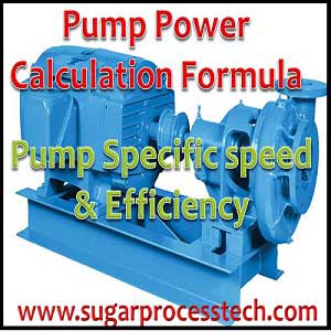
In this article provided pump related formulas like fluid flow rate and velocity, power calculation, Specific Speed of Pump (Nq), Total Head, Pump Torque and temperature rise, Net Positive Suction Head, Affinity laws for pump, Pump Efficiency & Overall Efficiency of the Pump

Basic required formulas for the operation of Pump

Reading Map - Quick Links

Toggle
  • Formulas regarding product while pumping
  • Pump Power Calculation
  • Specific Speed of Pump (Nq)
  • Total Head
  • Pump Torque and temperature rise
  • Net Positive Suction Head
  • Affinity laws for pumps
  • Pump Efficiency & Overall Efficiency of the Pump

Formulas regarding product while pumping

Volume of the fluid (Q )

 \text{Volume of fluid (l/sec)} = \frac{\text{Mass flow rate (kg/sec)} \times 1000}{\text{Density (kg/m}^3\text{)}}

Velocity of the Fluid ( V )

 V = \frac{Q}{A}

Here

V = Velocity of fluid in m/sec
Q =Volume of Fluid (m3/sec)
A = Pipe line area (m2)

  \text{Velocity of fluid in pipe} = \frac{\text{Discharge Flow Rate} \ (\text{m}^3/\text{hr})}{\frac{\pi}{4} \times \text{Pipe ID (m)} \times 3600}

 V = \frac{Q \times 353.6}{D^2}

V = Velocity of fluid in m/sec
Q =Volume of Fluid in m3/hr
A = Pipe line dia in mm

Reynolds Number of the fluid

 R_e = \frac{D \times V \times \rho}{\mu}

Here
D = Dia of the tube in meters

V = flui
d velocity in m/sec
ρ=
density of the fluid  (kg/m3)
μ = Absolute viscosity in Pas

Absolute viscosity of the fluid (μ )

μ =  υ x ρ

where:
υ = Kinematic viscosity (mm
2/s)
ρ = density of the fluid in kg/m3

μ = Absolute viscosity of the fluid in mPas

Darcy Friction Factor

 f_d = \frac{64}{R_e}

where:
fd
= friction factor (Darcy)
Re = Reynolds number

Pump Power Calculation

Hydraulic Pump Power

The ideal hydraulic power to drive a pump depends on liquid density , differential height to lift the material and flow rate of the material.

 \text{Hydraulic Power} = \frac{Q \, H \, \rho \, g}{1000}

Here 

  • Hydraulic power in watt
  • Q = Flow rate in M3/sec
  • H = Total head in meters  = Discharge head + Suction head
  • ρ = Density of the Fluid kg/dm3 (1 kg/m3 = 0.001 kg/dm3)
  • g = Acceleration due to gravity (m/sec2)

Pump Power input or Pump shaft Power

The pump power input of a centrifugal pump is the mechanical energy at the pump coupling or pump shaft absorbed from the drive.

 \text{Pump Shaft Power} = \frac{\text{Hydraulic Power}}{\text{Pump Efficiency}}

  \text{Pump Shaft Power} = \frac{Q \, H \, \rho \, g}{1000 \, \eta_p}

Here

  • Q = Flow rate in M3/sec
  • H = Total head in meters  = Discharge head + Suction head
  • ρ = Density of the Fluid ( kg/dm3)
  • ηp =Pump efficiency

Pump input power from pump shaft power

  \text{Electrical Input Power} = \frac{\text{Pump Shaft Power}}{\eta_m}

    • ηm =motor efficiency

Pump input power from current and voltage

  \text{Pump input power from current \& voltage} = \frac{\text{Current (A)} \times \text{Voltage (V)} \times \eta_m \times \eta_p}{57735}

Here all efficiencies are in decimals

Pump Efficiency and Pump Power Calculation Formulas with Examples

Specific Speed of Pump (Nq)

Specific Speed of pump (Nq) is identifies the geometrical similarity of pumps. It is useful to comparing different pump designs irrespective of pump size

 N_q = \frac{3.65 \times N \times Q^{0.5}}{H^{0.75}} = \frac{333 \times n \times \sqrt{Q}}{(g \times H)^{3/4}}

    • Nq = Dimensionless parameter
    • N = RPM of pump
    • n = Rev/sec of Pump
    • Q =  Flow rate in m3/sec
    • H = Head in meters
    • g = Gravitational constant ( 9.81 m/sec2)

Suction Specific Speed at best efficiency point

 N_s = \frac{N \times \sqrt{Q}}{(NPSH)^{3/4}}

    • Ns = Suction Specific speed of pump (Dimensionless parameter)
    • N = RPM of the pump
    • Q = Flow rate in M3/hr
    • NPSH = Net positive section head in meters

Total Head

In pumping system, Head means it is a height of a liquid column.

In vertical pipe any liquid coloumn of water exerts a certain pressure (force per unit area) on a horizontal surface at the bottom area, this pressure is expressed in metres of liquid column or kg/cm2.

H = Ht – (±Hs)

where:
H
t = total discharge head
H
s = total suction head

Total Discharge Head

Ht = ht + hft + pt

where:

    • ht = static discharge head
    • hft = pressure drop in discharge line
    • pt = Pressure head in delivery
      p
      t > 0 for pressure
      p
      t < 0 for vacuum
      p
      t = 0 for open tank

Total Suction Head

Hs = hs + hfs + (± ps)

    • where:
      h
      s = static suction head
      hfs = pressure drop in suction line
    • ps = Pressure head in suction
      p
      s > 0 for pressure
      p
      s < 0 for vacuum
      p
      s = 0 for open tank

Pressure Head for Pump

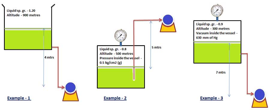
Pressure Head of the pump suction must be considered according to the condition of source tank.

Pressure head calculated as per pumping system source tank is under some gauge pressure or vacuum open or open to atmospheric than pressure head is calculated in metres of water column (MWC) of Feet of water column of liquid.

  \text{Head (meters)} = \frac{10.2 \times P \, (\text{bar})}{\text{Specific Gravity}}

pressure head calculation for pump NPSH

Velocity head

  H_v \, \left( \text{in } m \right) = \frac{V^2}{2g} = 0.0510 \, (V)^2 = \frac{6380 \, (Q)^2}{d^4}

Here

    • Hv = Velocity head in meters
    • V = Fluid velocity in m/sec
    • g = Gravitational constant (9.81 m/s2)
    • Q = Flow rate in m3/hr
    • d = pipe inside diameter in mm

Shutoff head :

Shutoff head of the centrifugal pump is the maximum head that can be developed by a pump operating at a set speed

Please go through the below link for more information about pump head

calulation of Pressure head, velocity head, friction head for pump NPSH

Pressure Head | Velocity head | Static Suction Head Calculation of PUMP

Pump Torque and temperature rise

 \text{Pump Torque (in } N\text{-m)} = \frac{9450 \times \text{Pump Power (kW)}}{\text{Pump Speed (rpm)}}

Temperature rise in pumps can be calculated as per the below formula

 \Delta T = \frac{P (1 - \eta_p)}{C_p \times Q \times \rho}

Here

    • ΔT = Temperature rise in the pump (in oC)
    • P = brake power (kW)
    • ηp =Pump efficiency
    • Cp = specific heat of the fluid (kJ/kg oC)
    • Q = Flow rate of the pump (m3/second)
    • ρ = fluid density (kg/m3)

Net Positive Suction Head

Net Positive Suction Head Required (NPSHr ):

The amount of NPSH the pump requires to avoid cavitation is called Net Positive Suction Head Required (NPSHr). This value of the pump is determined based on actual pump test by the vendor.

Net Positive Suction Head Available( NPSHa) :

Net positive suction head available is the difference between the saturation pressure and the pump suction pressure for the liquid being pumped.

The amount of  Net positive suction head available (NPSHa) to the pump from the suction line is termed NPSHa.

NPSHa = Absolute Pressure head + Static head (difference in elevation) – Vapor pressure head – Friction head loss in the piping, valves and fittings.

Net positive suction head available must be greater than or equal to the net positive suction head required to avoid cavitation. It can be stated mathematically as shown below.
NPSH a ≥ NPSH

Please go through the below link for more information about NPSH

Pump NPSH Calculation -sugarprocesstech.com

Formulas of pump NPSH and head loss calculation in suction and delivery line

Affinity laws for pumps

Change in Diameter

 \frac{D_1}{D_2} = \frac{Q_1}{Q_2} = \frac{\sqrt{H_1}}{\sqrt{H_2}}

 \frac{P_1}{P_2} = \frac{(D_1)^3}{(D_2)^3}

  • D = Diameter of the impeller (inch or mm)
  • Q = Flow rate (gpm or m3/hr)
  • H = Head (ft or m)
  • P = Power ( hp or kW)

Change in Speed

 \frac{N_1}{N_2} = \frac{Q_1}{Q_2} = \frac{\sqrt{H_1}}{\sqrt{H_2}}

 \frac{P_1}{P_2} = \frac{(N_1)^3}{(N_2)^3}

  • N = Pump speed (RPM)
  • Q = Flow rate (gpm or m3/hr)
  • H = Head (ft or m)
  • P = Power ( hp or kW)

Please go through the below link for more information about affinity laws

Affinity laws for centrifugal pumps | positive displacement pump affinity laws | affinity laws energy savings | pump affinity laws example with calculator

Affinity laws, Affinity laws for centrifugal pumps &  Positive displacement pump with example

Pump Efficiency & Overall Efficiency of the Pump

Generally for any system efficiency means the ratio of output and input

 \text{Efficiency of the system} = \frac{\text{Output}}{\text{Input}}

Pump Efficiency can be defined as a ratio of pump input and output power.

i.e Efficiency of the pump defined as the ratio of water horse power to break horse power.

Pump Efficiency:

 \text{Pump Efficiency} = \frac{\text{Pump Output}}{\text{Pump Input}} \times 100

Pump Efficiency using Horse Power:

 \text{Pump Efficiency} = \frac{\text{Water Horse Power}}{\text{Break Horse Power}} \times 100

Pump Efficiency using Hydraulic Power:

 \text{Pump Efficiency} = \frac{\text{Hydraulic Power}}{\text{Pump Shaft Power}} \times 100

Hydraulic Power in Watts:

 \text{Hydraulic Power} = Q \times H \times \rho \times g

Here

    • Q = Flow rate in m3/sec
    • H = Total developed head in meters
    • ρ  = Density in kg/m3

 \text{Hydraulic power in kW} = \frac{Q \times H \times \rho}{102}

Here

    • Q = Flow rate in Lt./sec ( 1 m3/sec = 3.6 x Lt./sec)
    • H = Total developed head in meters
    • ρ  = Density in kg/dm3 (Conversion : 1 kg/m3 = 0.001 kg/dm3)

Pump shaft power means it is an input to pump often is the output of motor.

In case of gear drive or pulley drive, efficiency of these drives will also have to be taken into account

Output of motor = (kW input to motor) x motor efficiency (ηm)

Input to motor is measured directly in kW. Then

 \eta_{p} = \frac{Q \times H \times \rho}{102 \times \text{kW input to motor} \times \eta_m}

Overall Efficiency of the pumping system

Overall efficiency (ηoverall) = Pump efficiency (ηp) x Motor efficiency (ηm)

 \eta_{\text{overall}} = \eta_{p} \times \eta_{m} = \frac{Q \times H \times \rho}{102 \times \text{kW input to motor}}

pump related formulas of Power calculation, Total Head, NPSH, Affinity laws, Efficiency of the pump

Related Articles:

Classification of pumps | Types of pumps and their working principles

NPSH Calculation |Head loss in suction and delivery line

Pump Vapour pressure calculation | Water Vapour Pressure Table at Different temperatures

Affinity Laws for Centrifugal and Positive displacement pumps

Pump Efficiency and Pump Power Calculation Formulas with Online Calculator

Pressure head, Velocity Head formulas with examples

Unit Conversion Factors and Tables for Engineering Design Calculations
Affinity laws for pumps NPSH Overall Efficiency of the Pump pump design formulas Pump efficiency pump efficiency formula pump power formula pump related formulas Specific Speed of Pump Total Head
Share. Facebook Twitter Pinterest LinkedIn Tumblr Email
sivaalluri333
  • Website

Related Posts

Terminology of Sugar Process Industry in Centrifugal Section

Terminology of Sugar process industry in Crystallization Section

Sugar Process Industry Terminology in Clarification Section | Sugarprocesstech

Leave A Reply Cancel Reply

  • Popular
  • Recent
  • Top Reviews
October 4, 2024

Phosphoric Acid (H3 PO4 ) Dosing in Sugar Industry | Online Calculator

October 3, 2024

Batch Centrifugal Machine Capacity and Gravity Factor Calculation

October 3, 2024

Definitions in Steam Properties and Online Steam Table For Saturated steam

October 4, 2024

Phosphoric Acid (H3 PO4 ) Dosing in Sugar Industry | Online Calculator

October 3, 2024

Batch Centrifugal Machine Capacity and Gravity Factor Calculation

October 3, 2024

Definitions in Steam Properties and Online Steam Table For Saturated steam

July 3, 2022

Boiler Efficiency Calculation by Direct Method with Example

May 19, 2022

Pump Related formulas | Power calculation, Total Head, NPSH, Affinity laws

August 25, 2020

Perimeter and Area Formulas for two dimensional geometrical figures

All Categories
  • Batch pans
  • Calculations
  • Calculations in Centrifugals
  • Calculations in Clarification
  • Calculations in Crystallisation
  • Calculations in Evaporation
  • Capacity calculations
  • Centrifugal Machines
  • Centrifugal Section
  • Clarification
  • Clarifier
  • Condensers
  • Continuos Pans
  • Crysatllisation
  • Distillery
  • Equipment Design & Drawing
  • ETP
  • Evaporation
  • General Articles
  • Juice Defication/Sulphitation
  • Juice heating
  • Lime and Sulphur
  • Material Balance
  • Mill and Diffuser
  • Molasses Conditioners/ Crystallizers
  • Power Plant
  • Pumps
  • Raw sugar
  • Robert/Kestner/FFE
  • Seminars & Carriers
  • Steam and Power
  • Sugar Engineering
  • Sugar House
  • Sugar Lab
  • Sugar Refinery
  • Sugar Tech
  • Terminology
  • Types of sugars
  • Vacuum Filters
  • WTP
Latest Galleries
Latest Reviews
About Us

sugar industry technologies - sugar technology -sugarprocesstechWelcome to sugarprocesstech.com, your go-to hub for invaluable insights into the complex world of sugar processing and related industries. Founded in 2017 by a seasoned sugar technologist with a wealth of experience, this platform is dedicated to sharing deep knowledge with fellow industry experts and the emerging generation of technologists.

IMP PAGES
About Us Sugar Tech Articles Capacity Calculation Important Links Online Calculators Thumb Rules Unit Conversion Contact Us

    Copyright © 2025 Sugar Process Tech | SivaRamaKrishana Alluri
    • About Us
    • Home
    • Sugar Tech
    • Sugar Engineering
    • Calculators

    Type above and press Enter to search. Press Esc to cancel.