In this article discussed about pressure head and velocity head definitions, pressure head calculation example at different source tank conditions. Also explained about various pressures like Absolute (ab) Pressure, Barometric Pressure, Gauge Pressure and Vacuum.
Pressure head formulas with example problems | Velocity Head and Suction for Pumps
The term Net Positive Suction Head (NPSH) is one of the important concepts in pump design. It is simple say ” Net” stands for remaining head and Positive stands for the head greater than Zero.
So Net head means the sum following heads act on pump suction
- Atmospheric Pressure Head
- Static suction head
- Vapour pressure head
- Velocity head
- Friction head
Now we discussed these concepts with example
What is head?
The height of a liquid coloumn is known as Head.
A coloumn of water or any liquid in a vertical pipe exerts a certain pressure (force per unit area) on a horizontal surface at the bottom, this pressure is expressed in kg/cm2 or metres of liquid column.
What is the atmospheric pressure?
Atmospheric pressure balances a column of mercury (Hg) to height of 760 mm at sea level or water column of 10.33 meters. The atmospheric pressure at sea level is 1.03323 kg/cm2 (ab) at normal temperature of 15.550C
| Altitude above mean sea level in metres | Atmospheric pressure in Kg/cm2(ab) or bar | Pressure in mm of Hg | Equivalent head of water in metres | Boiling point of water in oC |
| Sea Level | 1.03323 | 760 | 10.33 | 100 |
| 500 | 0.973 | 716 | 9.73 | 98.9 |
| 1000 | 0.916 | 674 | 9.16 | 96.7 |
| 1500 | 0.862 | 634 | 8.62 | 95 |
| 2000 | 0.812 | 597 | 8.12 | 93.3 |
| 4000 | 0.616 | 453 | 6.28 | 87 |
| 6000 | 0.472 | 347 | 4.81 | 81 |
Conversions
Conversion of Atmospheric pressure kg/cm2(ab) to mm of Hg
Example: Covert 0.472 Kg/cm2(ab) to mm of Hg
= 347 mm of Hg
= 760 – 347 = 413 mm of Hg
Conversion of mm of Hg to Atmospheric pressure kg/cm2(ab)
Example: Covert 453 mm of Hg to Kg/cm2(ab)
= 0.616 Kg/cm2(ab)
= 1.03323 – 0.616 = 0.417 Kg/cm2(ab)
Conversion of vacuum in mm of Hg to barometric column in mlc (metres of liquid column)
Formula :
Here V = vacuum gauge reading in mm of Hg
13.6 = Specific gravity of Mercury
Liquid specific gravity
For example 430 mm of Hg then find the water column required for the liquid of water
Sol: 430 x 13.6 / (1000 x 1 ) = 5.85 mlc ( water specific gravity = 1 )
Note : Altitude correction can be simply applied as 1 ft (0.3 m) for each 1000 ft (305 m) of elevation in the calculation of NPSH available.
Static suction head (Elevation head)
Static suction having basically two types of heads – positive suction head and negative suction head.
( Note: Technically the negative suction head is called as suction lift )
Static Suction Lift : This exists when the source of liquid is below the pump datum. So while NPSH calculation it attracts “-ve “ sign.
Static Suction Head : This exists when the source of liquid is above the pump datum. This is also called “flooded Suction“. So while NPSH calculation it attracts “+ve “ sign.
Pressure Head for Pump
Pump suction Pressure Head must be considered according to the source tank condition. When a pumping system source tank open to atmospheric pressure or under some gauge pressure or vacuum than pressure in such a tank must first be converted to metres of water column (mlc) of Feet of water column of liquid.
Pressure head calculation example for pump
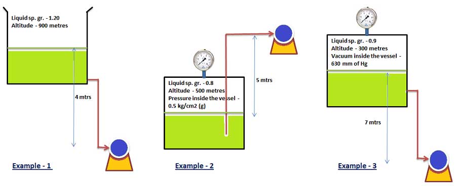
See the following examples for calculation of pressure head and static suction head
Example – 1 ( Source vessel in open atmospheric condition )
Pressure Head Calculation Formula
Site altitude 900 mtrs
Liquid specific gravity 1.20
According to site altitude atmospheric pressure to be convert into mlc (metres of water column)
Altitude correction = 0.001 x Altitude in meters. = 0.001 x 900 = 0.90 mtr
Corrected atmospheric Pressure = 10.03323 – 0.9 = 9.13 mtrs
Barometric Pressure = 9.13 / Liquid sp. Gr. = 9.13 / 1.20 = 7.61 mtrs
Condition of the source vessel – Open to atmosphere
Final pressure head = 7.61 mtrs
Suction head / suction lift
Elevation between source of liquid level to the pump datum line = 4 mtrs
Suction head = 4 mtrs
Example – 2 ( Source vessel is closed condition with gauge pressure )
Pressure Head Calculation
Site altitude 500 mtrs
Liquid specific gravity 0.8
According to site altitude atmospheric pressure in mlc (metres of water column)
Altitude correction = 0.001 x Altitude in meters. = 0.001 x 500 = 0.50 mtr
Corrected atmospheric Pressure = 10.03323 – 0.5 = 9.53 mtrs
Barometric Pressure = 9.53 / Liquid sp. Gr. = 9.53 / 0.8 = 11.91 mtrs
Condition of the source vessel – Closed tank under pressure 0.5 kg/cm2 (g)
So it has to be converted into absolute pressure in mlc (metres of water column)
= 0.5 x 10 / Liquid sp. Gr = 0.5 x 10 / 0.8 = 6.25 mlc
Total Pressure head = 11.91 + 6.25 = 18.16 mtrs
Suction head / suction lift
Elevation from source of liquid level to the pump datum = 5 mtrs
Suction lift = -5 mtrs
Pressure head example problems – 3 ( Source vessel is closed condition under vacuum with gauge pressure)
Pressure Head Calculation
Site altitude 300 mtrs
Liquid specific gravity 0.9
According to site altitude atmospheric pressure in mlc (metres of water column)
Altitude correction = 0.001 x Altitude in meters. = 0.001 x 300 = 0.30 mtr
Corrected atmospheric Pressure head = 10.03323 – 0.3 = 9.73 mtrs
Barometric Pressure head = 9.73 / Liquid sp. Gr. = 9.73 / 0.9 = 10.81 mtrs
Condition of the source vessel – Closed tank under vacuum 630 mm of Hg
So it has to be converted into absolute pressure in mlc (metres of water column)
= 630 x 13.6 /( 1000 x Liquid sp. Gr) = 630 x 13.6 /( 1000 x 0.9) = 9.52 mtrs
Total Pressure head = 10.81 – 9.52 = 1.29 mtrs
Suction head / suction lift
Elevation from source of liquid level to the pump datum = 7mtrs
Suction head = 7 mtrs
Note: For general calculation purpose altitude consider mean sea level and pressure head for open tanks considered as 10.03323 mtrs.
Definitions for various pressures
Absolute (ab) Pressure : It is the pressure above absolute Zero. it may be above or below atmospheric pressure
So If the pressure 2.0 kg/cm2(ab) means positive atmospheric pressure ( above 1.03323 kg/cm2(ab) )
If the pressure 0.5 kg/cm2(ab) means negative atmospheric pressure ( below 1.03323 kg/cm2(ab) )
Barometric Pressure: It is atmospheric pressure at the locally being studied and varies mainly with the altitude and slightly with atmospheric conditions.
Gauge Pressure: It is the pressure above atmosphere at the locality
Vacuum : It is a negative gauge pressure i.e below atmospheric pressure. So vacuum always read like mm of Hg or in abs terms.
Velocity head
Velocity Head Definition: This represent kinetic energy in a mass of flowing fluid in a pipe and measured in metres.
Velocity Head is expressed by the formula
V = Velocity of liquid in m/sec
g = Acceleration due to gravity (9.81 m/sec2)
Velocity head description : Velocity head is also theoretically the height that a jet would attain while coming out from a vertical nozzle in horizontal pipe line. It is the function of a fluid velocity in pipe.It varies according to the static in vessel.
Generally suction pipe design about the velocity 1 m/sec or less depends upon type of liquid
So according to the above formula = 1 / 19.6 = 0.05 mtrs
While calculating Pump Net Positive Suction Head (NPSH) Velocity head is impact is very less.
Vapour pressure head purpose go through the below link
Vapour pressure definition | Vapour pressure of water at different temperatures from 0 0C to 370 0C | Vapour pressure head of liquids calculation for NPSH
Friction head calculation for pump
Friction head in pump suction line can be defined as it is a lost head due to friction in suction line between source tank and pump inlet flange.
NPSH calculation friction loss in pipe suction line is negligible while following these parameters
1 . Velocity of flow in the suction line shall me maintained 1 m/sec or less depend upon the fluid characteristics.
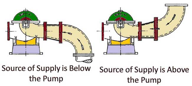
2. Always suction shall be design without bends. If bend required bends then choose only long bends not used short bends
3. Source of supply is below the pump then eccentric reducer should be arranged with top flat like below figure.
4. Source of supply is above the pump then eccentric reducer should be arranged with bottom flat like below figure or concentric reducer also can be used.
 For more information go through the below link
Formulas for head loss in suction and delivery line
Related Articles:
Pump Affinity Laws for Centrifugal and Positive displacement pumps
Classification of pumps | Types of pumps and their working principles
We hope this page “Calculation of Pressure head, velocity head, friction head for pump NPSH ” fulfill your requirement. So we requested you please give feed back, comments to improve this and don’t forget to share it


2 thoughts on “Pressure Head | Velocity head | Static Suction Head Calculation of PUMP”
Giorgi
(December 27, 2018 - 1:22 pm)Greetings,
Please let me know velocity Head impact is positive or negative with net pressure? Velocity Head increasing or decreasing the pressure? thanks in advance
Bandu Chaure
(January 6, 2019 - 3:14 pm)Thanku sir
it is very needful knowldge for me