")
Thermal Power plants play a key role in meeting energy demand in Sugar industries as well as process industries. Biomass-based Cogeneration plants, especially bagasse-fired boilers, are widely used because they efficiently utilize the by-product of sugar production. Coal is also used as a supplementary fuel during the off-season for Power generation to export Power.
This article provides an overview of thermal power plants, including their classification based on fuel, steam cycle, and configuration, components, working principle, flow diagrams, boiler systems, process flows of steam, water, Biomass, Fuel & Flue Gas, and pollution control systems, with clear and simple explanations suitable for students, professionals, and industry technologists.
What Is a Thermal Power Plant?
A thermal power plant is a facility where heat energy from fuel combustion is converted into mechanical energy, and then into electrical energy using a steam turbine and generator. In the sugar industry, thermal plants are usually Cogeneration plants, producing electricity and process steam simultaneously.
Classification of Thermal Power Plants
Thermal power plants are classified based on Fuel, Steam Cycle & Power Cycle Configuration.
Based on fuel
- Biomass-based: Uses renewable fuels such as Bagasse, wood chips, rice husk, and cane trash to generate steam and power. Commonly used in sugar industries.
- Coal-fired: Uses coal as the primary fuel for continuous and stable power generation, especially during off-season operation.
- Lignite-based: Uses low-grade brown coal (lignite) and is usually located near lignite mines due to fuel transportation limitations.
- Oil-fired: Uses furnace oil or diesel, generally for small capacity plants or as standby/emergency power sources.
- Gas-fired: Uses natural gas, offering fast start-up, high efficiency, and lower emissions compared to coal plants.
Based on the Steam Cycle
- Subcritical: Operates below the critical pressure and relies on traditional boiling to generate steam, making them the most common design in older plants.
- Supercritical: Operating above the critical pressure, where water directly converts to steam without boiling, thereby improving efficiency and reducing fuel consumption.
- Ultra-supercritical: Push steam conditions further with higher pressure and temperature to achieve the highest thermal efficiency and lower emissions in modern plants.
| Type of Steam Cycle | Typical Pressure Range | Typical Steam Temperature Range |
|---|---|---|
| Subcritical | < 22.12 MPa | Approximately 510–565 °C |
| Supercritical | ≈ 22.12 – 25 MPa | Approximately 565–600 °C |
| Ultra-Supercritical | > ≈ 25 MPa | Above 600 °C |
Most sugar mill cogeneration plants use subcritical boilers, typically in the range of 67–110 kg/cm², because they offer:
-
- Proven reliability
- Lower capital cost
- Easier operation and maintenance
Based on Power Cycle Configuration
- Condensing: In a condensing power plant, all the exhaust steam from the turbine is condensed in a surface condenser. The main objective is to generate maximum electrical power, and no steam is used for process heating. This type is commonly used in large utility power stations.
- Back-pressure: In a back-pressure power plant, the exhaust steam from the turbine is not condensed and is supplied directly to the process at a required pressure. This type is suitable where process steam demand is more important than power generation.
- Extraction-cum-condensing: In this configuration, part of the steam is extracted from intermediate stages of the turbine for process use, while the remaining steam is further condensed. This system provides a balanced combination of power generation and process steam supply.
- Combined Heat and Power (CHP) / Cogeneration (commonly used in sugar mills): A CHP or cogeneration plant produces electricity and useful process steam simultaneously from the same fuel. This configuration offers high overall efficiency and is most commonly used in sugar mills, where steam is required for juice heating, evaporation, and crystallization.
| Power Cycle Type | Steam Utilization | Typical Application |
|---|---|---|
| Condensing | All steam condensed | Utility power plants |
| Back-Pressure | All steam is used for the process | Process industries |
| Extraction-Cum-Condensing | Part process, part condensed | Industrial cogeneration |
| CHP / Cogeneration | Power + process steam | Sugar industry |
Overview of Thermal Power Plant – Main Components
A modern biomass- or coal-based thermal power plant consists of several major systems that work together to generate steam, produce electricity, and safely handle fuel, flue gas, and waste. Each system has a specific function, as explained below.
In sugar industries, travelling grate or spreader stoker boilers are commonly used for biomass and coal firing.
A modern biomass/coal-based power plant includes the following major sections:
1. Fuel Handling System: The fuel handling system is responsible for receiving, storing, and supplying fuel to the boiler at a controlled rate.
- Bagasse Handling: Bagasse from the sugar mill is conveyed using belt conveyors and fed to the boiler through bagasse feeders.
- Coal Handling: Coal is received in a yard, crushed if required, and conveyed to the boiler through conveyors.
- Storage Yard: Provides buffer storage to ensure continuous boiler operation.
2. Boiler / Steam Generator: The boiler is the heart of the power plant. It converts water into high-pressure and high-temperature steam.
- Fuel is burned in the furnace.
- Heat released from combustion is transferred to water through water walls, boiler tubes, and heat recovery sections.
- Steam is generated in the steam drum and further heated in the superheater.
3. Air & Flue Gas System: This system supplies air for combustion and removes flue gases from the boiler.
- FD Fan (Forced Draft): Supplies fresh air to the furnace.
- SA Fan (Secondary Air): Provides additional air above the grate for complete combustion.
- ID Fan (Induced Draft): Draws flue gases through the boiler and pollution control equipment to the chimney.
Proper air and flue gas management ensures efficient combustion and safe operation.
4. Water–Steam Cycle: The water–steam cycle recovers and reuses water to generate steam continuously.
- Deaerator: Removes dissolved oxygen and gases from feed water.
- Boiler Feed Water Pump (BFWP): Pumps water to the boiler at high pressure.
- Economizer: Preheats feed water using flue gas heat.
- Superheater: Increases steam temperature before entering the turbine.
This cycle improves thermal efficiency and equipment life.
5. Steam Turbine & Generator: High-pressure superheated steam rotates the turbine to produce mechanical energy.
- The turbine shaft rotates the generator.
- The generator converts mechanical energy into electrical energy.
- In sugar mills, extraction cum condensing or back-pressure turbines are commonly used to supply process steam.
This section is responsible for power generation.
6. Cooling System
The cooling system condenses exhaust steam from the turbine.
- Condenser: Converts exhaust steam into water by removing heat.
- Cooling Tower: Rejects heat to the atmosphere and cools circulating water.
The condensed water is reused, reducing water consumption.
7. Ash Handling System
Ash produced during fuel combustion must be collected and disposed of safely.
- Bottom Ash: Collected from the furnace bottom.
- Fly Ash: Collected from flue gas using pollution control equipment.
Ash is transported to silos or disposal areas, maintaining clean plant operation.
8. Pollution Control Equipment
These systems reduce environmental emissions from the power plant.
- Multicyclone: Removes coarse dust particles.
- Electrostatic Precipitator (ESP): Removes fine particulate matter.
- Wet Scrubber: Reduces dust and gaseous pollutants like SOx.
These systems help meet environmental regulations.
9. Electrical & Instrumentation System
This system ensures safe, reliable, and automated operation of the plant.
- Power distribution systems and switchgear.
- Control panels, sensors, transmitters, and protection systems.
- Distributed Control System (DCS) for monitoring and control.
Accurate instrumentation improves efficiency and plant safety.
Working Principle of Thermal Power Plant (Step-by-Step)
Fuel Preparation: Bagasse or coal is collected, crushed (if required), and conveyed to the boiler through fuel handling systems to ensure a continuous and uniform fuel supply.
Combustion: The fuel is burned inside the boiler furnace on a travelling grate. Proper air supply from FD and SA fans supports complete combustion and releases heat energy.
Heat Transfer: The heat produced in the furnace is transferred to water through:
Economizer → Water walls → Boiler bank → Superheater
Steam Generation: The steam drum separates water and moisture vapour, and dry steam goes to the superheater.
Superheating: The dry steam passes through the superheater, where its temperature is raised to about 515°C, making it suitable for efficient turbine operation.
Steam to Turbine: High-pressure, high-temperature steam enters the steam turbine and expands through turbine blades, causing the turbine shaft to rotate. Steam expands and rotates the turbine.
Power Generation: The rotating turbine shaft drives the generator, converting mechanical energy into electrical energy. A turbine drives a generator to produce electricity.
Steam Condensation: After expansion in the turbine, the exhaust steam enters the condenser, where it is cooled and converted back into water (condensate).
Water Recovery: The condensate is reused through the following path. This closed cycle reduces water consumption and improves efficiency.
Condensate → deaerator → feed pump → economizer → drum → boiler.
Flue Gas Path: The hot flue gases produced during combustion flow through heat recovery and pollution control equipment
Furnace → superheater → economizer → air heater → ESP → chimney.
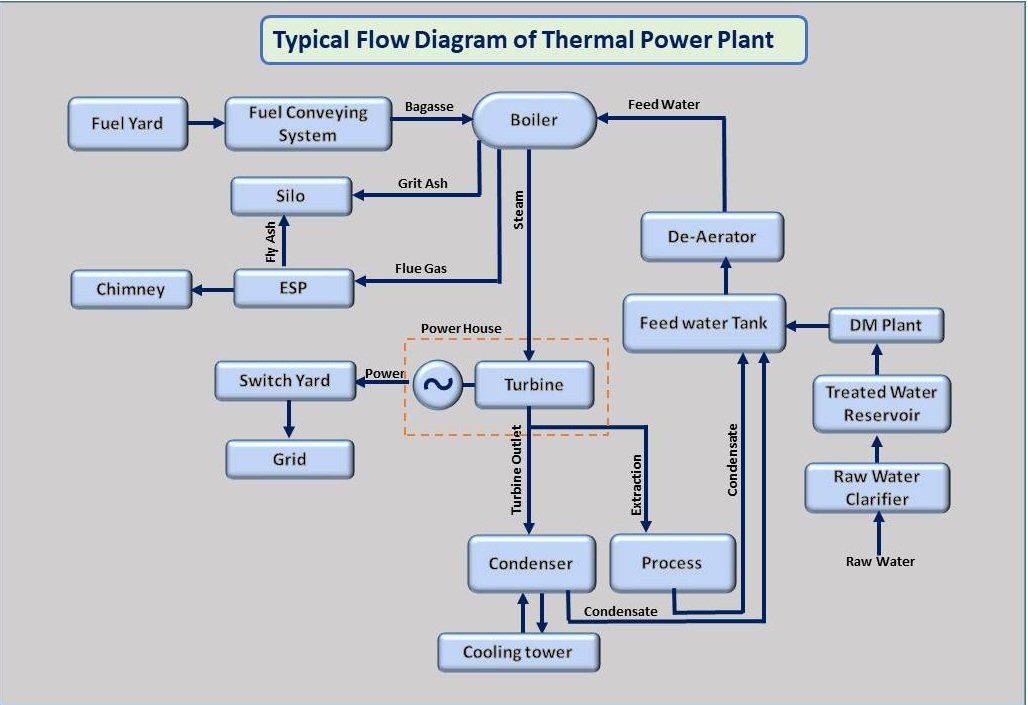
Process Flow of Water, Biomass, Fuel & Flue Gas
Water–Steam Cycle: The water–steam cycle converts feed water into steam, generates power, and recovers water for reuse.
Water → Deaerator → Feed Water Pump → Economizer → Steam Drum → Water Walls → Steam → Superheater → Turbine → Condenser → Deaerator.
Fuel Flow (Bagasse/Coal): Fuel flow ensures continuous and controlled combustion inside the boiler.
Fuel Yard → Conveyors → Feeders → Grate → Combustion → Ash → Ash Handling System
Air Flow: Air flow supplies oxygen for combustion and improves burning efficiency.
Atmospheric Air → FD Fan → Air Heater → Undergrate Air Secondary Air → SA Fan → Over Fire Air
Flue Gas Flow: Flue gas flow recovers heat and controls pollution before releasing gases to the atmosphere.
Furnace → Superheater → Economizer → Air Heater → ESP / Scrubber → Chimney
 Pollution Control System
During operation, a thermal power plant generates different types of pollutants. Proper control systems are required to protect the environment.
Thermal power plants generate pollutants such as:
- Particulate matter (SPM): Fine dust and ash particles are carried with the flue gas from the boiler. If not controlled, these particles can pollute the surrounding air.
- SOx & NOx: Sulphur oxides (SOx) and nitrogen oxides (NOx) are formed during fuel combustion. These gases contribute to air pollution and acid rain.
- Thermal pollution: Hot water discharged from condensers and cooling systems can increase the temperature of nearby water bodies if not properly cooled.
- Solid & liquid waste: Solid waste mainly consists of ash from fuel combustion, while liquid waste includes boiler blowdown and wastewater from plant operations.
- Noise pollution: High noise levels are produced by equipment such as turbines, fans, pumps, and compressors, which can affect workers and nearby areas.
Pollution Control Equipment Used in Thermal Power Plants: To reduce pollution and protect the environment, thermal power plants are equipped with the following control systems:
- Multicyclone: A multicyclone removes large and heavy dust particles from the flue gas using centrifugal force. It is usually the first stage of dust removal.
- Wet Scrubber: A wet scrubber uses water to wash the flue gas and remove fine dust particles and sulphur oxides (SOx). Reduces particulate matter + SOx, and it also helps in reducing gas temperature.
- Electrostatic Precipitator (ESP): An ESP removes very fine dust particles from the flue gas by using an electric field. It is highly efficient and can remove more than 99% of particulate matter before the gas is released through the chimney.
These systems ensure environmental compliance and reduce impact on surrounding areas.
Thermal power plants play an important role in meeting the energy and steam requirements of sugar and process industries. Biomass and coal-based cogeneration plants efficiently convert fuel energy into useful electricity and process steam, making them highly suitable for sugar mills. By using proper boiler technology, optimized steam cycles, and effective pollution control systems, thermal power plants can operate reliably while minimizing environmental impact.
Understanding the basic working principle, classification, main components, and process flows of a thermal power plant helps students, engineers, and industry professionals to better design, operate, and maintain these systems.
If you found this article useful, feel free to share it with fellow professionals and students in the power and sugar industries.
Related Article:
- Definition of steam properties like enthalpy, sensible heat, latent heat, total heat, supersaturated steam, and also given steam table for saturated steam.
- Boiler efficiency and its formula for the direct method of calculation.
- Need for Boiler Feed water Treatment | Boiler water treatment process.
- Economizer heating surface and Its Outlet Flue Gas Temperature Calculation.