NPSH Calculation and Find pump suction and delivery line head loss with online calculator
Net Positive Suction Head (NPSH):
Net positive suction head is the term that is usually used to describe the absolute pressure of a fluid at the inlet to a pump minus the vapour pressure of the liquid. The NPSH is always positive since it is expressed in terms of absolute fluid column height in meter head or feet head. The term “Net” refers to the actual pressure head at the pump suction flange and not the static suction head. A minimum amount of suction pressure (head) is needed for a pump to operate without cavitation.
When discussing centrifugal pumps, the two most important head terms are NPSHr and NPSHa.
Net Positive Suction Head Required (NPSHr ):
The amount of NPSH the pump requires to avoid cavitation is called NPSHr. NPSH required is a function of the pump design and is determined based on actual pump test by the vendor.
Net Positive Suction Head Available( NPSHa) :
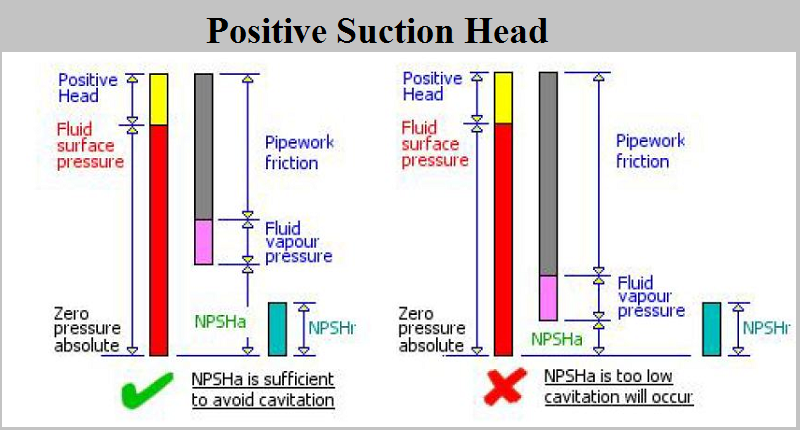
The amount of NPSH available to the pump from the suction line is termed NPSHa. And also NPSHa is defined as:
NPSHa = Pressure head + Static head – Vapor pressure head of your product – Friction head loss in the piping, valves and fittings.
Pressure Head (hp):
Pressure head refers to absolute pressure on the surface of the liquid reservoir supplying the pump suction, converted to feet of head or meter of head. If the system is open, hp equals atmospheric pressure head.
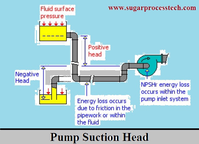
Static Suction Head (hS) :
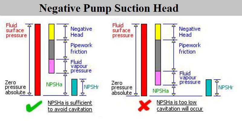
Head resulting from elevation of the liquid relative to the pump center line. If the liquid level is above pump center line, hS is positive. If the liquid level is below pump center line, hS is negative. Negative hS condition is commonly denoted as a “suction lift” condition.
Vapour Pressure Head (hvp):
The vapour pressure of liquid can be obtained from vapour pressure tables. When the vapour pressure is converted to head, it is referred to as vapor pressure head, hvp. The value of hvp of a liquid increases with the rising temperature and in effect, opposes the pressure on the liquid surface, the positive force that tends to cause liquid flow into the pump suction i.e. it reduces the suction pressure head.
Friction Head (hf):
The head required to overcome the resistance to flow in the pipe and fittings. It is dependent upon the size, condition and type of pipe, number and type of pipe fittings, flow rate, and nature of the liquid.
Comparison of NPSHa and NPSHr :
All calculated values must be in the same units either meter head or feet head. If the NPSHa is greater than the NPSHr cavitation should not occur. If the NPSHa is lower than the NPSHr then gas bubbles will form in the fluid and caviation will occur.
Increasing the NPSH available :
To increase the NPSHa consider the following:
a) Increase the suction pipe work size to give a fluid velocity of about 1 m/sec or 3 ft/sec
b) Redesign the suction pipe work to eliminate bends, valves and fittings where possible.
c) Raise the height of the fluid container.
d) Pressurized the fluid container, but ensure that the pressure in the container is maintained as the fluid level is lowered.
Cavitation:
Liquid entering the impeller eye turns and is split into separate streams by the leading edges of the impeller vanes, an action which locally drops the pressure below that in the inlet pipe to the pump. If the incoming liquid is at a pressure with insufficient margin above its vapour pressure, then vapour cavities or bubbles appear along the impeller vanes just behind the inlet edges. This Phenomenon is known as cavitation and has three undesirable effects:
a) The collapsing cavitation bubbles can erode the vane surface, especially when pumping water-based liquids.
b) Noise and vibration are increased, with possible shortened seal and bearing life.
c) The cavity areas will initially partially choke the impeller passages and reduce the pump performance. In extreme cases, total loss of pump developed head occurs.
Avoiding cavitation :
In a system where the pipe work layout provides a positive head, the motive force to move the fluid to the pump will be the fluid surface pressure plus the positive head. Incorrect sizing of the supply pipe work and isolating valves may result in high frictional losses which can still lead to situations where the NPSHa is still too low to prevent cavitation.
Reynolds number (R ):
This is a dimensionless coefficient which characterizes the nature of the flow, whether laminar or turbulent:
R = U x D / v
R = Reynolds number
U = fluid velocity, in m/sec
D = pipe diameter, in meters
v = kinematic viscosity of the fluid = μ g / ω in m/s
μ = absolute viscosity of the fluid, in kg s /m2
ω = density of the fluid, in kg/m3
g = gravity factor = 9.8 m/sec2
When R < 2,320, the flow is laminar, When R > 3,000, the flow is turbulent, When R lies between these two values, the flow is unstable and may be either laminar or turbulent. The values 2,320 and 3,000 are called the upper and lower critical values of the Reynolds number.
Resistance coefficient of pipe line ( λ ):
This coefficient depends on the nature of the flow, in other words on the Reynolds number R.
Laminar flow : we shall take value for λ = 64 / R
Turbulent flow : With turbulent flow, X depends also on the state of the interior surface of the pipe.
Smooth pipes. For R <100000 λ = 1 / (100R)0.25
For R> 100000 than take λ = 0.0032+ [0.221/ R0.237]
Rough pipe : . When the Reynolds number is very high – (105 to 106, according to roughness), we may take λ = 0.01(A/D)0.314
D = interior diameter of the pipe, in (ft.)
A = coefficient having the dimension of length, if take A= 1.5 for new metal , relatively smooth , A= 2.5 for new cast iron or steel, A= 5 for old rusted lines
(Note : In below calculator consider formulas only 0.0032+ [0.221/ R0.237] for R value below one lack , λ = 0.01(2.5/D)0.314 for R value from one lack to ten lack and λ = 0.01(5/D)0.314 for R value more than ten one lack)
Head loss due to pipe line length in pump suction and delivery( J ):
pressure drop (or loss of head) along the pipe, in m (ft.) head of liquid. In the same way, the head loss may be expressed per unit length of pipe
J =[ λ/D] / (U2 /2g]
U = mean velocity of flow of the liquid, in m/s
g = gravity factor = 9.8m/sec2
D = diameter of pipe, in mtr
J= unit loss of head, in per meter length pipe
λ = Resistance Coefficient of pipe
Head loss of fittings in suction and delivery lines( I ) :
Pressure drop (or loss of head) along the bends or fittings of pipe line, in m (ft.)
I = K x U2 / 2g
U = mean velocity of flow of the liquid, in m/s
g = gravity factor = 9.8m/sec2
K = Resistance coefficient for particular fitting.
I = Head loss for that fitting in meters.
Online Calculator for Pump NPSHa calculation and also find head loss in pump suction and delivery lines
(Note: Here gave two types of calculators. One is for sugar process industry pumps and another for general purpose pumps. The difference of these two types of calculators is no need to enter the values of fluid density and dynamic viscosity in sugar process industry pump calculator.)
Sugar Industry Pumps
General Pumps
Related Articles
Pump Vapour pressure calculation | Water Vapour Pressure Table at Different temperatures
Classification of pumps | Types of pumps and their working principles
Pump Affinity Laws for Centrifugal and Positive displacement pumps
Pump Efficiency and Pump Power Calculation Formulas with Online Calculator
Pressure head, Velocity Head formulas with examples
Unit Conversion Factors and Tables for Engineering Design Calculations
Rotary vacuum filter Equipment capacity details in sugar industry.
Role of Bagacillo in vacuum filter | bagacillo cyclone Capacity Calculation.
Need of Boiler Feed water Treatment | Boiler water treatment process.
Hi friends Thanks for reading. I Hope you liked it. Give feed back, comments and please share it
5 thoughts on “Formulas of pump NPSH Calculation |Head loss in suction and delivery line”
اغاني
(September 23, 2017 - 1:28 am)Hi,I check your blog named “Formulas to Find pump NPSH, Head loss in suction and delivery lines with online calculator” regularly.Your writing style is awesome, keep it up! And you can look our website about اغاني.
siva alluri
(September 23, 2017 - 3:47 pm)Thank you sir
The “www.sugarprocesstech.com” invites to all sugar technologists to share your knowledge, achievements in your working organization and new developments and technologies in sugar industry and its concerned units. It is very much helpful to show your identity to the world at the same time it will helpful to another technologist to enhance their insight and enhance great execution in there working. This website also provides the basic knowledge in sugar industry technologies and equipment design calculation with online calculators.
sugarprocesstech@gmail.com
Aniket shedbale
(May 20, 2019 - 1:37 am)It is best for direct calculations of npsh, time required for other terms are saved, thank for this page
siva alluri
(May 22, 2019 - 3:03 pm)Thank you Mr.Aniket shedbale
fathy elhenawy
(July 26, 2022 - 1:46 pm)NPSH a calculation detailes