In this Article discussed about different steps in effluent treatment plant ( ETP ) like Bar Screening, Oil and grease removal , Primary and secondary Clarifier, Anaerobic Treatment Process, Activated sludge process, Activated Gravity Separator, Multi-grade or Duel media filter, Sludge management system for Sugar industry waste treatment.
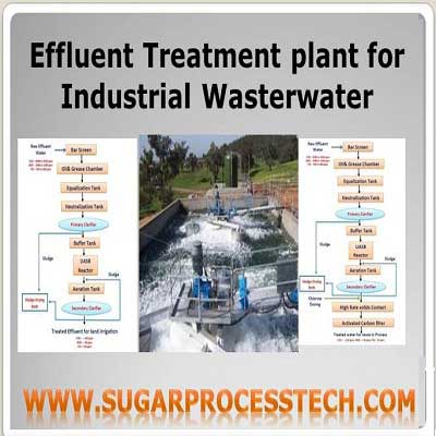
Effluent Treatment Plant (ETP) in Sugar Factory | Liquid Waste Management in Sugar Industry
Types of waste generation from sugar factories
Liquid waste
Solid waste
Gaseous waste
Out of these wastes liquid waste generated as follows
1. Mill house – cleaning and Washing, Juice leakages, Spillages of mill bearing water
2. Boiling house – Chemical boiling and tube cleaning of evaporator and pans, Excess condensate water, pump leakages, Daily and periodical cleanings and washings, laboratory and domestic water usage
3. Spray pond over – Blow down of spray pond water
4. Boiler blow down
5. Power plant cooling tower blow down.
Basic Concepts of Effluent treatment Plant ( ETP )
1. Quality of treated water maintained as per standard parameters of treated effluent.
2. Under any circumstances stringent regulatory norms for discharge are met.
3.As far as possible it keeps the environment clean & free from contamination.
4. Minimal electricity consumption, less chemical consumption with low operation & maintenance cost.
General Parameters of raw effluent water generated in sugar industry
pH – 4.0. to 6.5
Chemical oxygen Demand ( COD) – 2000 to 3000 mg /lt.
Biological oxygen demand (BOD ) – 1000 to 1200 mg /lt.
Total Suspended solids (TSS) – 500 to 600 mg/lt.
Total Dissolved Solids ( TDS) – 5000 to 6000 mg/lt.
Oil and grease – 10 to 50 mg/lt.
Standard parameters of treated effluent water
| S.No | Parameters | Standard norms | Inland surface water | Land for irrigation |
| 1 | pH | 6.5 to 8.5 | 5.5 to 9.0 | 5.5 to 9.0 |
| 2 | Total solids | < 2000 | – – – | – – – |
| 3 | Suspended solids | < 300 | < 100 | < 200 |
| 4 | Chemical oxygen demand (COD) | < 250 | < 250 | – – – |
| 5 | Biological oxygen demand (BOD) | < 100 | < 30 | < 100 |
| 6 | Oil &grease | < 10 | < 10 | < 10 |
Note: In some cases COD of treated effluent water is maintained < 150 ppm and BOD is < 30 ppm.
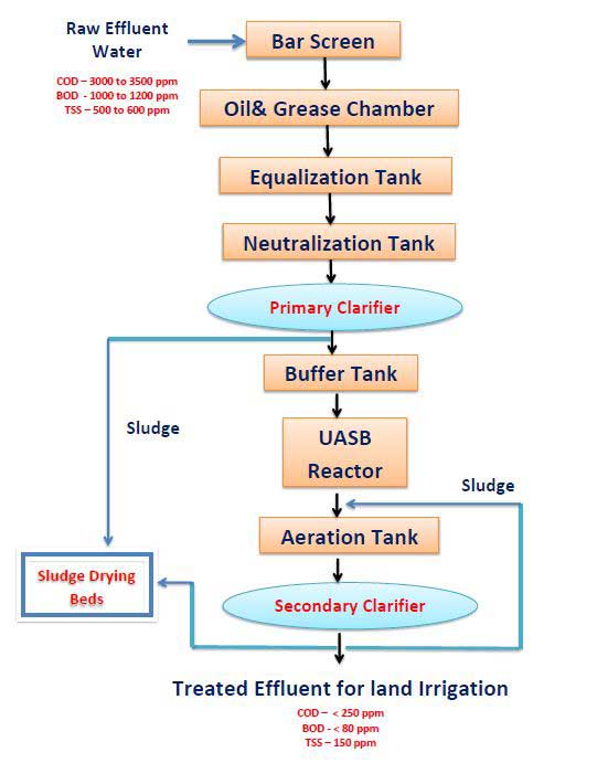
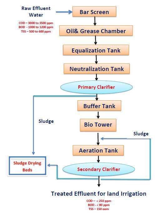
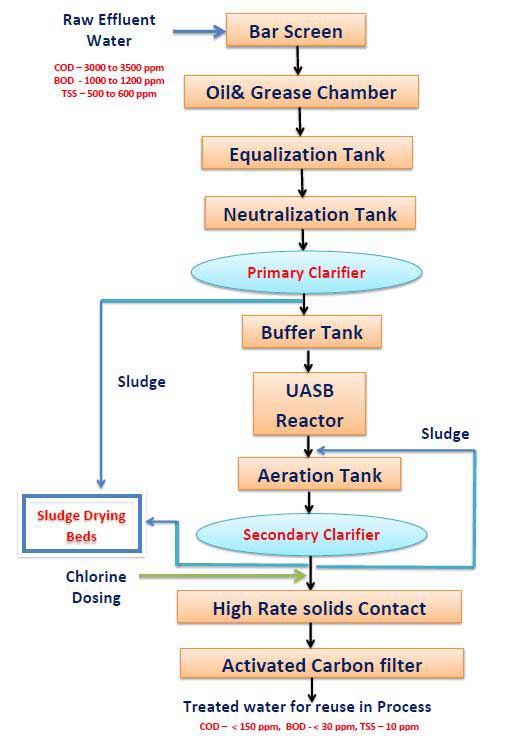
Different Steps in Wastewater Treatment Philosophy
The process design involves Physico-chemical and Biological processes. The treatment process will be chosen as per our final requirement of treated water parameters.
Physico-Chemical Treatment
Screening
Oil and grease removal by skimming
Equalization or Homogenization of effluent
Dosing of chemical for maintained neutral pH of effluent
Primary and secondary Clarifier- solid liquid separation
Chlorination system
Activated Gravity Separator
Activated Carbon filter
Multi-grade or Duel media filter
Sludge management system ( i.e Centrifuge or sludge drying beds)
Biological Treatment
Anaerobic Treatment Process ( i.e Anaerobic decomposition with Anaerobic digester).
Activated sludge process ( i.e Bio-tower or Aerobic decomposition in extended aeration tank or Aerobic Lagoon Treatment)
Screening
The untreated effluent contains bigger suspended solids and floatable matter like bagasse which contributes organic and inert matter that needs to be removed from effluent.
The untreated industrial effluent is first passed through the fixed bar screens where all the bigger suspended solids and floatable matter get separated and removed.
The screened effluent is then taken to the oil and grease removal tank by gravity.
Oil & Grease Trap
Untreated sugar effluent stream contains some Oil & Grease, which may cause clogging in mechanical equipment. Also seriously affect the working of other Subsequent treatment units of biological treatment.
The sugar effluent from Bar Screen Chamber would be received in the Oil & Grease (O & G) removal chamber by gravity. Oil and Grease will float to the surface of the tank during the detention period (half an hour) and are removed with the help of some mechanical equipment like Oleophilic, belt type oil skimmer.
Equalization of effluent
The raw effluent is allowed into the equalization tank, and is mixed continuously with a floating aerator or air diffused system to homogenize the combined effluent from different sources of the plant and to maintain the uniform characteristics of the effluent.
Equalization tank will be to even out the fluctuations in the flow and quality of raw effluent and to ensure supply of steady and uniform flow of the composite effluent both in terms of flow and quality to the subsequent treatment units.
This aerator will be operated as per requirement, and adjust itself according to the liquid level in the tank.
Neutral pH of effluent
Generally the effluent having low pH value. So the equalization tank are thoroughly mixed by dosing lime or caustic soda or soda ash in the equalization tank to neutralize the pH of the raw effluent before letting into the other subsequent units.
Primary clarifier
The neutralized effluent from Equalization Tank is pumped to the primary clarifier. Here different types of primary clarifier ( like conventional type or lamella type) are used to removing suspended solids. The supernatant from the clarifier enter into next treatment unit. Sludge from the clarifier is sent to the sludge drying beds.
Anaerobic Treatment
In Anaerobic treatment decomposition of the organic matter in the absence of oxygen. In this process the sludge is converted biologically into a variety of end products including methane & CO2.
For more information regarding this process please go through the below link.
Anaerobic Reactor – Up Flow Anaerobic Sludge Blanket Reactor (UASB)
Fixed film anaerobic reactor is referred as an anaerobic bio-digester where anaerobic microorganisms grow on the rough surface of media.
It treats the high degree organic effluents with minimal energy and also gives useful bio-gas rich of methane.
Effluent from Feed Tank is continuously fed to Anaerobic Reactor by Raw effluent transfer pump to the reactor.
The anaerobic organisms will degrade the high concentrated complex organic matter present in the effluent. In this reactor plastic media is used as a medium to adhere microorganisms.
The anaerobic reactor COD will be removed by 70% to 80 %.
Activated sludge process
In activated sludge process, the microbial population is thoroughly mixed with in coming waste water in a suspended form. The Bio-purification consists of converting the suspended and particulate organic matter in the raw waste water into harmless end products and new cells growth.
The effective and efficient operation of the biological Activated Sludge Process depends on the maintenance of a steady-state condition. This means that the best operation should be carried out without any sudden changes in any of the variables.
For more information regarding this process please go through the below link.
Activated Sludge Treatment of Industrial waste water
Bio-Tower
The aerobic organisms will degrade the high concentration organic matter present in the effluent. In this tower plastic media is used as a medium to adhere to microorganisms, which will in turn convert the complex organic matter into simple compounds.
Effluent from the previous treatment is taken to the sump of the Biotower by gravity from where it is pumped to the top of the Biotower. Effluent is sprayed on the bio-fills / Plastic media arranged and supported by the crossbeams in the Biotower.
Part of the effluent is recycled from the sump and the balance from this unit is collected in the Settling tank or Lamella clarifier .
Overflow From settling Tank the effluent is pumped into the next step of the treatment system.
Biotower is an aerobic filter where BOD reduction of around 65% and COD reduction of 50% is possible. It is designed on the basis of attached growth biodegradation by bacteria.
It generally precedes the Activated Sludge Process (ASP) to reduce the electrical consumption of ASP and to reduce overall foot print area of the treatment system.
Extended Aeration tank
Aeration tank can be referred to an aerobic biological reactor. Aeration tank is a holding tank where the effluent will be mixed with the bacterial population. In the presence of oxygen and nutrients, bacteria consumes organic pollutant as “ FOOD” and convert them as harmless by products.
The raw effluent transferred to aeration tank by gravity or pumping from previous treatment unit. The feed to aeration tank is in a controlled manner according to system handling capacity and performance.
Air blowers with diffused aeration system of suitable capacity are provided at the aeration tank. Blowers will introduce atmospheric oxygen (air) into the contents of the aeration tank, which will be consumed by bacterial culture during aerobic oxidation of organic matter.
Mechanical Surface aerator is also used in aeration tank for high efficient aeration which gives oxygen from the atmosphere. At the same time by stirring it provides agitation and mixing in the water to disperse the oxygen and to keep solids in suspension.
The aerated effluent is allowed to overflow to the clarifier mechanism in sedimentation of the suspended matter presence in the effluent the sludge is recycled to the aeration tank to maintain desired mixed liquor suspended solids (MLSS) concentration and food to microorganism ratio ( F/M).
Secondary Clarifier:
Each kilogram of BOD destroyed will generate approximately 0.45 – 0.80 kg sludge depending upon operating conditions.
To maintain suitable mixed liquor suspended solids (MLSS ) concentration in the aeration tank, the excess sludge generated has to be drained, otherwise, the bacterial population in the aeration tank will be very high.
The bacteria being nourished in the aeration tank has certain life cycle and beyond, which they die. Dead bacteria being organic, they also contribute to residual BOD and oxygen demand.
As per quantity of sludge from the secondary clarifier is pumped back to the aeration tank and the remaining is drained and sent to the sludge management system for further treatment.
The clarifier is a hopper bottom circular tank with centrally drive clarifier mechanism. In clarifier solids get settled at the hopper bottom. The supernatant from the clarifier overflows uniformly over the peripheral launder and enter into treated effluent tank.
Chlorination tank
The treated waste will further be subjected to chlorination for disinfection. Chlorine in the form hypochlorite solution for disinfection and oxidation of residual COD. Chlorine dosing will be adjusted to maintained the residual chlorine concentration of 0.5 to 1.0 ppm.
Multigrade Filter
Chlorinated effluent is pumped to multigrade filter for removal of suspended solids.
Multigrade filter consists of a cylindrical mild steel vessel with dished ends. Filter media in the form of sand and gravel are provided.
Treated wastewater will be received at the suction of multigratde filter feed transfer pump. Filter feed pump tranfer the treated wastewater to downstream of MGF and treated water collected from upstream of the same.
The MGF will have to be back washed at sufficient time interval or whenever the differential pressure exceeds 1.0 kg/cm2(g) across the filter.
Activated carbon filter ( ACF)
Activated carbon filter is used for removal of suspended solids, colour and odor. Activated carbon filter consist of a cylindrical mild steel vessel with dished ends. Activated carbon used as a filter media.
High Rate solids Contact Clarifier (HRSCC) or Accelerated Gravity Separator (AGS)
High rate solid contact clarifier shall be provided for removal of residual suspended collodial particles from the treated effluent.
The HRSCC unit consists of central reaction zone and peripheral settling zone. Alum shall be added as a coagulant agent.
Settled sludge will be removed continuously along the floor towards center of unit by means of a slowly rotating scraper.
Sludge Management System
The excess sludge from the Primary, Secondary clarifiers should be dewatered before final disposing. The dried sludge can be used as excellent manure due to the high concentration of Nitrogen and Phosphorous in it.
Sludge drying beds
Sludge Drying Beds properly dewater and dry the sludge, which is easy to dispose.
Excess sludge from Primary, Secondary clarifier is taken in to the sludge drying beds. The filtrate is collected through individual and main drains of sludge drying beds, which will be taken to the equalization tank by gravity or pump. The sludge cake remaining on the surface will be used as fertilizer in agricultural forms.
Different types of effluent water treatment ( ETP ) schemes in sugar industry to various application
Process flowchart of treatment of effluent water for Land application ( with UASB Reactor)
Process flowchart of ETP for Land Application ( with complete Activated Sludge process)
Process flowchart of ETP for reuse of water to process
Thank you for reading this article “ Effluent treatment Plant ( ETP ) for Sugar Industrial waste water ”. We hope that, this article was full filled your requirement. Give feed back, comments and please share it.
Related Articles:
Anaerobic Digestion | Activated Sludge Process for Wastewater Treatment
Anaerobic Treatment Process for Industrial Waste Water
Various methods for Industrial Effluent Treatment Plant
Distillery Spent Wash Treatment by Biomethanation Process
Anaerobic Digester |Continuous Stirred Tank Reactor Design Criteria | CSTR


8 thoughts on “ETP | Sugar industry effluent treatment plant process philosophies”
srinivas
(June 25, 2019 - 9:24 am)Shiva it is very good information and understanding the ETP operation.Thank you shiva.
Nisheeth Sharma
(July 25, 2019 - 10:46 am)We have One MGF and One AGF of 2mx1.7m our tss is high do we have to change the media pl let me know
siva alluri
(July 31, 2019 - 3:39 pm)How much TSS you get. Give me full details then we will suggest
NISHEETH SHARMA
(August 15, 2020 - 12:54 pm)Our t s s are seldom high will bid cod etc will be correspondingly high for eg if our TSS is 143 then what should be the corresponding BOD and COD
Manoj Kumar Mishra
(March 8, 2021 - 10:38 am)Pl. provide calculation for spend wash quantity . We used thick juice & syrup as feedstock then BOD and COD in spend wash is same or different
mahesh
(November 23, 2021 - 8:15 am)super
siva alluri
(January 2, 2022 - 9:01 am)Thanks
V Jagtap
(October 4, 2022 - 9:47 am)Respected All,
We JAGTAP Engineering Works can help you setting-up the New ETP Plant for Sugar mill raw water treatment.
If any sugar factory planning for setting up ETP for their sugar mill factory then please provide your raw water parameters,
Mail ID: vjagtap1356@gmail.com
Thank you,
JAGTAP Engineering Works,
Vijay Jagtap