In this article explained about basic concepts of cooling tower, types of cooling towers, formula for cooling tower efficiency. Also brief about Cooling tower mass balance of make-up water requirement in system, Drift Losses or Windage, Evaporation losses & Blowdown or Draw off.
Types of cooling tower | Cooling Tower Basic Calculations
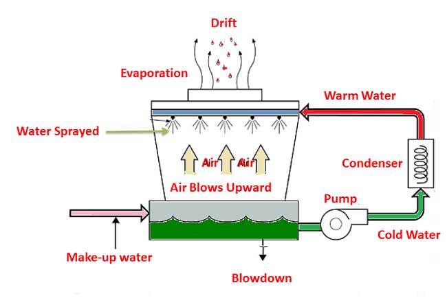
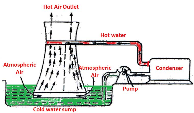
Cooling towers are a very important part of many process plants and power plants. The make-up water source is used to refill water lost to evaporation. Hot water from heat exchangers/condenser is sent to the cooling tower. After reducing the temperature of water in cooling tower and is sent back to the condenser /exchangers or to other units for further process.
 Terminology in Cooling Tower
Drift: From a cooling tower water lost due to liquid droplets entrained in the exhaust air. It is independent of water lost by evaporation.
Heat exchange/ Condenser – It is a device for transferring heat from one substance to another.
Concentration : The process of increasing solids per unit volume of solution also the amount of material dissolved in a unit volume of solution.
Usually concentration of liquid in cooling tower occurs due to evaporation that cools the water. It is normally expressed directly as (parts per million) ppm or indirectly as mhos conductivity.
Air Blows: By the opening in cooling tower through which air enters a tower.
Blowdown: Water discharged from the system of cooling tower to control concentration of salts or other impurities in the circulating water
Evaporation loss: In the process of cooling tower system, water evaporated from the circulating water into the atmosphere.
Makeup : Water added to the circulating water in cooling tower system to replace water lost by evaporation, blowdown, drift and leakage
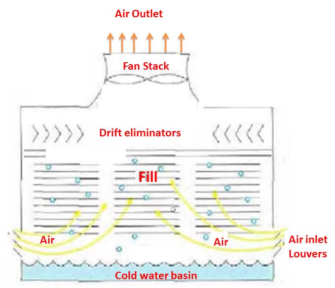
Drift eliminators: An assembly constructed of plastic, cement board, wood, or other material that minimize the entrained water moisture from the discharged air.
Cooling water : Water circulated through a cooling system to remove heat from certain areas.
Exhaust air : The mixture of air and its associated vapor leaving the cooling tower system
Louvers : Members installed horizontally in a cooling tower wall to provide openings through which the air enters into the system while also containing the falling water within the tower. Usually Louvers are installed at an angle to the direction of air flow to the cooling tower.
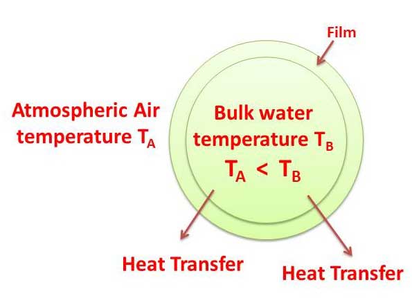
Fundamental Concept of Cooling Tower : Heat is transferred from water drops to the surrounding atmospheric air by the transfer of latent heat and sensible heat.
Types of Cooling Towers
Cooling towers mainly classified into two sub-divisions
1. Mechanical draft cooling tower
2. Natural draft cooling tower
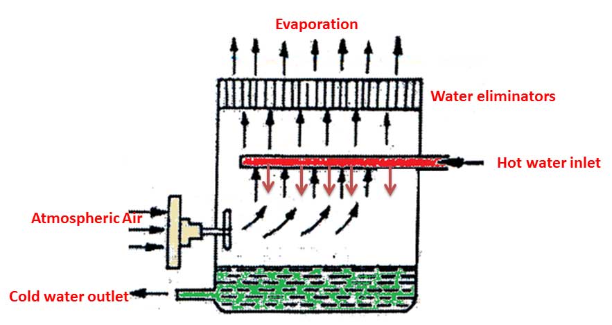
Mechanical draft water-cooling tower:
Mechanical draft cooling towers are more commonly used for cooling of water. These mechanical draft cooling towers utilize large fans to force air through circulated water. The water falls downward over surface of fills, which help increase the contact time between the air and water. This helps maximize heat transfer between the air and water.
Mechanical draft water-cooling tower consists mainly two types
a) Forced draft – In this cooling tower fans located at the air inlet
b) Induced draft – In this cooling tower fans located at the air exhaust.
Forced draught cooling tower
These take the form of a large rectangular concrete structure. The water is pumped to the top and broken up into sprays. It falls as rain on to successive stages of boards in the form of louvres of wood, polystyrene or metal, with notches and ribs to break up the flow. The water flows from one stage to the next and finally arrives at the pond which forms the base of the structure, from which it is taken by the cold water pump.
In a forced draught cooling tower, as shown in figure. The circulation of air in forced draft cooling tower is produced by means of fans placed at the base of the tower
Induced draught cooling tower
In an induced draught cooling tower, as shown in below figure. The circulation of air is provided by means of fans placed at the top of the tower.
They are generally induced draft cooling tower classified as counter current or cross flow tower, descriptive of the direction of air flows relative to that of the water.
The counter current tower is expected to be more efficient, but the cross flow tower can be operated with lower power requirement or higher vapour velocities.
Induced Draft Cooling Tower – Counter Current Flow type
Induced Draft Cooling Tower – Cross Flow type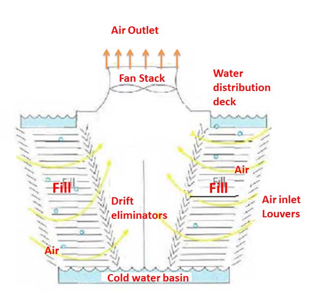
Natural draft water-cooling tower
The cooling tower, generally packed with brushwood or wooden laths. This is a very large tower in which the hot water encounters a natural draught which promotes cooling of the water by convection and evaporation.
In a natural draught cooling tower, as shown in figure the circulation of air is produced by the pressure difference of air inside and outside the cooling tower
Design Considerations of cooling tower
The efficiency of this device depends essentially on climatic conditions, in particular the wet-bulb temperature and the relative humidity of the ambient air.
The required cooling tower design and size will be a function of following values
a) Cooling range
b) Web bulb temperature
c) Approach to wet bulb temperature
d) Mass flowrate of water (Circulation rate)
e) Air velocity through tower or individual tower cell
f) Tower height
The performance of cooling towers is estimated by approach and range. During the performance assessment, portable monitoring instruments are used to measure the following parameters:
a) Dry bulb temperature of air
b) Wet bulb temperature of air
c) Cooling tower inlet water temperature
d) Cooling tower outlet water temperature
e) Electrical readings of pump and fan motors
f) Exhaust air temperature
g) Water flow rate
h) Air flow rate
Operation Considerations of cooling tower (Cooling tower mass balance)
Cooling tower mass balance gives an indication about make-up water requirement in system. Cooling Tower Makeup is required due to water losses resulting from Drift, Evaporation & Blowdown.
Water make-up (M ) = Total water losses = Drift Losses ( D) + Evaporation Losses (E ) + Blow down Losses (B)
M = D + E + B
M = Make up water Requirement in m3/hr
D = Drift Loss in m3/hr
E = Evaporation Loss in m3/hr
B = Blow Down in m3/hr
Drift Losses (D) or Windage
Drift losses may be assumed to be:
D = 0.3 to 1.0 percent of Circulating water (C ) for a natural draft cooling tower
D = 0.1 to 0.3 percent of Circulating water (C ) for an induced draft cooling tower
D = about 0.01 percent or less of Circulating water (C ) if the cooling tower has windage drift eliminators
Evaporation Losses (E )
It is calculated on the basis of heat balance around the cooling tower
where:
C = Circulating water in m3/hr
= Latent heat of vaporization of water = 540 kcal/kg (or) 2260 kJ / kg or
Ti – To = water temperature difference from tower top to tower bottom in °C ( cooling tower inlet hot water and outlet cold water temperature difference)
Cp = specific heat of water = 1 kcal/kg / °C (or) 4.184 kJ / kg / °C
Alternatively to find the evaporation loss by the following formula (Reference: Perry’s Chemical Engineers Hand Book)
Evaporation loss in m3/hr = 0.00085 x 1.8 x circulation rate in m3/hr x (Ti-To) in 0C
( Hint: Theoretically the evaporation quantity for every 1,000,000 kCal heat rejected to evaporate 1.8 m3 of water)
Blowdown or Draw off
The process of cooling water circulates the cooling tower part of water evaporates thereby increasing solids per unit volume of solution also the amount of material dissolved in a unit volume of solution.
To control the Cycle of Concentration blow down or Draw off is given. Blowdown can be calculated from the formula
B = E/ (COC-1)
B = Blow Down (m3/hr)
E = Evaporation Loss (m3/hr)
COC = Cycle of Concentration.
Cycle of Concentration (COC)
The cycle of concentration is a dimensionless number. It is a ratio between parameter in Cooling Water to the parameter in Makeup water. It can be calculated from any the following formulae.
Cycles of concentration (COC) = Silica in Cooling Water / Silica in Makeup Water
Cycles of concentration (COC) = Ca Hardness in Cooling Water/ Ca Hardness in Makeup water
Cycles of concentration (COC) = Conductivity of Cooling Water / Conductivity of Makeup water
Cycles of concentration (COC) = Concentration of chlorides in circulating water /Concentration of chlorides in make-up water
The cycle of concentration (COC) normally varies from 3.0 to 7.0 depending on the Process Design and Manufactures Guidelines. In some large power plants, concentration cycles of the cooling tower may be much higher.
Cooling Tower Efficiency Calculations
The efficiency of this cooling tower system depends on climatic conditions, in particular the wet-bulb temperature and the relative humidity of the ambient air.
The required cooling tower design and size will be a function of following values
a) Cooling range
b) Web bulb temperature
c) Approach to wet bulb temperature
d) Mass flowrate of water (Circulation rate)
e) Air velocity through tower or individual tower cell
g) Tower height
In this calculation Cooling Tower Approach & Cooling Tower Range are important factors
Cooling Tower Approach
Approach: The difference between the Cooling Tower Outlet water (Cold Water Temperature) and ambient Wet Bulb Temperature is called as Approach of Cooling Tower.
Approach of cooling tower = Cooling tower outlet water – Wet bulb temperature
Cooling Tower Range
Range: The difference between the cooling tower inlet temperature (Hot Water Temperature) and cooling tower outlet temperature (Cold water temperature) is called Range of Cooling Tower.
Range of cooling tower = Cooling tower inlet temperature – Cooling tower outlet temperature
Cooling Tower Efficiency Formula:
Cooling Tower Efficiency
Or Simply
Cooling Tower Efficiency
In practice, the cooling tower efficiency will be in between 65 to 70%. In summer season the ambient air wet bulb temperature raises when compared to winter season so cooling tower efficiency limiting in summer season.

Related Articles:
Water Cooling System | Difference Between Cooling Tower and Spray Pond
Surface Condenser | Difference Between Jet Condenser and Surface Condenser
Pump Power Calculation Formula | Specific speed of a centrifugal pump
Pressure head formulas with example problems | Velocity Head and Suction for Pumps
Condenser System for vacuum creations and its types with design criteria
Thanks for reading this article. I Hope it may fulfill your requirement regarding the ” Fundamental concepts of Cooling tower system”. Give feed back, comments and please don’t forget to share it
16 thoughts on “Cooling tower basics calculation formulas | Cooling Tower Efficiency”
NEERAJ KUMAR RAJPUT
(June 5, 2019 - 2:56 pm)Calculation of armec cooling towar
Senthil Kumar Balasubramanian
(October 11, 2019 - 7:10 am)Dear Sir,
send the calculation
Mayank sharma
(January 16, 2020 - 10:13 am)Pl. Define approch again
Martin Castro
(January 23, 2020 - 8:26 pm)Thanks! Great article.
siva alluri
(January 24, 2020 - 3:24 pm)welcome
BALU KAYANDE
(April 15, 2020 - 6:36 am)very nice & simply explanation. Thank you.
siva alluri
(April 26, 2020 - 11:59 am)Thank you
dama goostar
(September 12, 2020 - 10:57 am)Dama Gostar Company has started its activity in Mashhad since 2001 and moved to Tehran after a short period and today it is considered the founder and innovative idea in the construction of low consumption hybrid cooling towers. Today, the company has 16 cooling tower models with the aim of improving the quality of its products for productivity in different climatic regions. All types of cooling towers manufactured by Dama Gostar Company today are supervised by the best quality control (QC) team and are made available to the general public.
Andrew
(December 19, 2020 - 8:56 am)Thanks for your article. Very informative . Send me on my email.. Thanks
KAILASNATHAN AKKAL
(March 14, 2021 - 12:03 pm)Hi,
We have a 1000 MW CCGT plants with 4GTs and 2 STs. Our ST condenser cooling through open loop sea water cooling ; i.e sea water goes through condenser and back to outfall channels to Sea. I am thinking of converting this design to closed loop cooling water through a cooling Tower. Could you please help me with the design calculation and the project cost for such a design change. What is the expected energy efficiency improvement by this design.
Kailash
Nelson V. Franco
(August 25, 2022 - 10:47 am)VERY USEFUL IN TEACHING THIS SUBJECT N THE FIELD OF MECHANICAL ENGINEERING. THANKS.
siva alluri
(October 1, 2022 - 3:51 pm)Welcome
Shakeel Sarwar
(May 29, 2023 - 8:54 am)Fine information
Shakeel Sarwar
(May 29, 2023 - 8:54 am)Fine information
siva alluri
(June 8, 2023 - 2:22 pm)Welcome
DAUD S A
(September 17, 2023 - 11:40 am)TERIMA KASIH SANGAT MEMBANTU PROSES PEMBELAJARAN YANG SUDAH DISERTAI DENGAN GAMBAR YANG SANGAT MUDAH DIMENGERTI