This article discussed about 80 MT capacity batch vacuum pan design calculation of Heating surface, Number of tubes, Dia of the downtake and tube plate, Graining volume, Dia of the vapour doom, Height of the top cone, Dia of vapour inlet and outlet pipe lines , Pipe line dia of noxious gases, Dia of condensate pipe line, Dia of Massecuite discharge, Calendria shell thickness and tube plate thicknesses
Batch Vacuum Pan Calculation in sugar industry | Crystallization process
Capacity required for crystallization process equipment like supply tanks, Capacity of Batch/continuous pans, condensers, molasses conditioners, spray pond, crystallizers capacity .. etc.
Please go throuh the below link for complete information regarding the above topics
Capacity Calculation of Pan Section
Basic design aspects of vacuum pan
Design of 80 MT capacity Batch Pan
1. Heating Surface :
Heating surface calculated on the basis of S/V ratio
For batch pan with 3rd vapour has a heating medium it will be 6.6 to 6.7 m2/m3
Formula = S/ V = 6.6
Srike volume = Weight/density of massecuite = 80 MT / 1.42 MT / m3 = 56.33 m3 ≈ 57 m3 = 570 HL
Heating surface required = 57 x 6.6 = 376 m2
2. Number of tubes
Generally, the specification of tubes for batch vacuum pan as follows
102 mm OD / 16 g ( 1.625 mm) / 800 mm length
Formula : S = Π x D x L x N
Here S = heating surface area of the pan in m2
D = Mean dia of tube in m ( OD – thickness of tube )
D = 102 – 1.625 = 100.375 mm
L = Effective Length of the tube in m ( Total length – 2 x Tube plate thickness – 2 x Tube expansion elevation and projection of the tube )
L = 800 -( 2 x 32) – (2 x 5) = 800 – 64 – 10 = 726 mm
N = Number of the tubes
So N = 376 / ( 3.14 x 0.726 x 0.100375 ) = 1643 nos.
3. Dia of the Downtake and tube plate:
Formula : Area of the tube plate =
Here N = Number of the tubes
P = Pitch of the tube in m
Considered 20% extra area to arrange vapour distribution in calendria of batch vacuum pan
Here first we calculate dia required for down take
It is calculated on the basis of circulation ratio of the pan and it is generally maintained minimum 2.5
Total cross section area of the tubes (A) in m2 = N x ( Π /4) x ID2
A = 1643 x 0.785 x ( 0.09875)2 = 12.58 m2
Area of the down take ( AD )in m2 = 12.58 / 2.5 = 5.032 m2
Dia of the down take = = 2.53 m = 2500 mm
Pitch of the Tube
Legment of the tubes for vacuum pan = 16 mm
So Pitch of the tube = OD + legment + Tube tolerance + Hole tolerance
Pitch of the tube P = 102 + 16 + 0.5 + 0.1 = 118.6 mm
Area of the tube plate A in m2= 1643 x 0.866 x (0.1186 )2 x 1. 2 + 5.032
A = 24.02 + 5.032 = 29.05 m2
Dia of the tube plate ( DTP) in m =
DTP = 6100 mm
Generally, dia of the downtake maintained 40% on tube plate dia for proper circulation of massecuite in pan.
Here 6100 x 40 % = 2440 mm ( As per above calculation it is 2500 mm. So it is OK )
4. Graining volume the batch vacuum pan
Please go throuh the below link for complete information regarding this topic
The Concept of Graining Volume of the Batch Pan
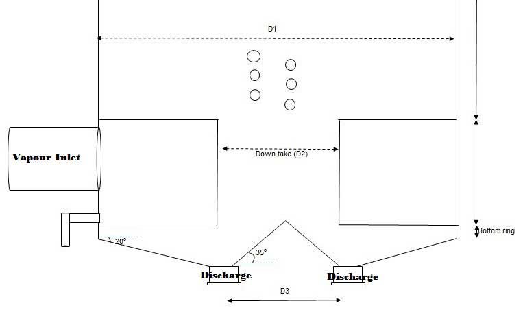
| Sl.no. | Description | Formula | Values | UOM |
| Input Data | ||||
| 1 | Capacity of pan | 80 | T | |
| 2 | No. of tubes | N | 1643 | nos. |
| 3 | Tube thickness | t | 1.6 | mm |
| 4 | Tube Length | H1 | 800 | mm |
| 5 | Tube OD | OD | 102 | mm |
| 6 | Dia of pan | D1 | 6100 | mm |
| 7 | Dia of the down take | D2 | 2500 | mm |
| 8 | Dia of bottom inverted cone | D3 | 2200 | mm |
| 9 | Height of the bottom ring | H2 | 50 | mm |
| 10 | Angle of bottom cone | α | 18 | Deg |
| 11 | Angle of bottom inverted cone | Φ | 35 | Deg |
| Graining Volume Calculation | ||||
| 1 | ID of the tube | ID = OD – 2t | 98.8 | |
| 2 | Volume of massecuite in tubes | Q1 = 0.785 x ID x ID x H1 x N | 10.07 | M3 |
| 3 | Volume of down take | Q2 = 0.785 x D2 x D2 x H1 | 3.93 | M3 |
| 4 | Volume of the bottom ring | Q3 = 0.785 x D1 x D1 x H2 | 1.46 | M3 |
| 5 | Height of the bottom cone | h 1 = [(D1 – D3)/2 ] x TAN α | 633.59 | mm |
| 6 | A1 | 0.785 x (D1)2 | 29.21 | M2 |
| 7 | A2 | 0.785 x (D3)2 | 3.80 | M2 |
| 8 | Volume of the bottom cone | Q4 = h/3 (A1+A2+√A1A2) | 9.20 | M3 |
| 9 | Height of the bottom inverted cone | h2 = [( D3)/2 ] x TAN Φ | 770.23 | mm |
| 10 | Volume of inverted cone | Q5 = 1/3 x 0.785 x (D3)2 h2 | 0.98 | M3 |
| 11 | Graining Volume | Q1+Q2+Q3+Q4 – Q5 | 23.68 | M3 |
| 42.0 | % | |||
5. Srike height:
Formula : Strick height ( Hs) in m = Volume of the massecuite above the tube plate in m3 / ( 0.785 x ID2 of the vapour space in m)
Here
Volume of the massecuite above the tube plate = Strike volume – graining volume
= 57 m3 – 23.68 m3 = 33.32 m3
ID of the vapour space = ID of the tube plate = 6100 mm – ( 2 x thickness of the vapour shell)
= 6100 – (2 x 16) = 6068 mm
Hs = 33.32 / [0.785 x (6.068)2] = 1.152 m = 1150 mm
6. Dia of the vapour dome
Dia of the vapour doom in meters ( Dd )=
Here
Volume of the vapour = Heating surface of pan x Evaporation rate x Specific volume of the vapour at 700 mm of Hg vacuum
Evaporation rate of the batch vacuum pans depends on type of the massecuites
Average evaporation rate in Batch Pans considered as follows
For ‘A ‘ Massecuite – 60 kg/m² /hr ,
For ‘B’ Massecuite – 55 kg/m² /hr
And for ‘ C’ Massecuite – 50 kg/m² /hr
So volume of the vapour = 376 x 60 x 11.04 = 249062 m3 /hr ( )
= 249062 / 3600 = 69.18 m3 /sec
Vapour velocity through the doom to be considered as 25 m/sec
Dd = √ 1.27 x ( 69.18 / 25 ) = 1.874 m ≈ 1900 mm
7. Height of the top cone part
Formula : Height of the top cone HTC = 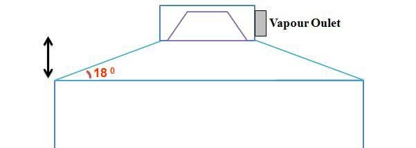
Here DTP = ID of the tube plate in mm = 6100 – (2 x 16) = 6068 mm
Dd = Dia of the top doom = 1900 – (2 x 18) = 1864 mm
∝ = Angle of the cone = 18o ( Generally, it in the range of 18 to 20)
HTC = [ (6068 – 1864) /2 ] x Tan 18o
= 2102 x 0.325 = 683 mm
8. Vapour inlet and outlet line dia
Vapour Inlet pipe dia =
| S.No | Description | Value | UOM |
| 1 | Heating surface of the pan | 376 | m2 |
| 2 | Evaporation rate | 60 | kgs/m2/hr |
| 3 | Pan Inlet Vapour Temperature | 94 | oC |
| 4 | Pan Outlet Vapour Temperature | 52 | oC |
| 5 | Pan Inlet Vapour Velocity | 35 | m/sec |
| 6 | Pan Outlet Vapour Velocity | 55 | m/sec |
| Result | |||
| 1 | Specific volume of Pan inlet vapour | pan boiling calculation2.0510 | M3/kg |
| 2 | Specific volume of Pan Outlet vapour | 10.98 | M3/kg |
| 3 | Volume of the pan inlet vapour | 12.853 | M3/sec |
| 4 | Volume of the pan outlet vapour | 68.81 | M3/sec |
| 5 | Pan Inlet vapour Line Dia | 0.684 | mtrs |
| Say | 700 | mm | |
| 6 | Pan Outlet vapour Line Dia | 1.262 | mm |
| Say | 1300 | mm | |
9. Vapour space height (Free space above the massecuite level upto top cone )
Generally, Vapour space required above the massecuite level is minimum 1500 mm.
10. Noxious gases connections
Generally, For removal of non-condensable gases required 1 cm2 area for 10 m2 heating surface of vacuum pan
SO Cross section area of non-condensable gases pipe line in cm2 = Heating surface in m2 /10
= 376 /10 = 37.6 cm2
Dia of the each non condensable gases pipe line =
Here considered 6 nos. of non condensable connections.
So Dia of the each non condensable gases pipe line = √ 376 / (0.785 x 6 ) = 2.82 cm ≈ 32 mm
Non condensable gas connections = 32 mm x 6 nos.
11. Dia of massecuite discharge
Dia of the massecuite discharge =
Strike Volume = 56.33 m3
Time required for massecuite discharge = 10 to 15 min.
Velocity of massecuite = 0.15 m/sec
Dia of the massecuite discharge = √ 56.33 / ( 0.785 x 12 x 60 x 0.15 ) = 0.815 m ≈ 800 mm
12. Dia of Condensate piping
Generally, for 80 MT pan condensate withdrawal points required minimum 2 nos. It is better to go with 3 nos. of connections.
Dia of the each condensate line =
Volume of the condensate = [Heating surface X Evap. Rate ] / [ Density of water x 3600].
= 376 x 60 / ( 1 x 3600 )
= 22.560 / 3600 = 0.00627 m3 /sec
Dia of the each condensate line = √ 0.00627 / ( 0.785 x 1 x 3 ) = 0.052 ≈ 80 mm
13. Calendria shell thickness
Formula : Calendria shell thickness ( ts ) in mm =
Here
P = Hydraulic test pressure in kg/cm2 = 3 kg/cm2
Di = ID of the Calendria in mm = 6100 – ( 2 x 16) = 6068 mm ( Here 16 mm considered for shell thickness for calculation purpose)
F = Allowable stress in kg/cm2 = For Mild steel it sis considered as 1400 kg/cm2
J = Welding Joint efficiency in mm = 0.75 mm
C= corrosion allowance in mm = 3.0 mm
t s ={ 3.0 x 6068 / [ ( 2 x 1400 x 0.75 ) – 3 ] } + 3 = 12 mm
But according to standard specifications calendria and body shell plate thickness for 80 MT pan is 18 mm and for bottom saucer is 25 mm
14. Tube Plate thickness
Tube plate thickness ( tp) in mm =
Here F =
K =
Here
C . A = corrosion allowance in mm = 1.5 mm
f = Allowable stress in kg/cm2 = 1400kg/cm2
P = Design pressure in kg/cm2 = 2.72 kg/cm2
Es = Modulus factor for MS sheet in kg/cm2 = 2.1 x 10⁶ Kg/cm2
Et = Modulus factor for SS sheet in kg/cm2 = 1.9 x 10⁶ Kg/cm2
G = ID of the shell in mm = 6068 mm
ts = Thickness of the shell in mm = 18 mm
tt = Thickness of tube in mm = 1.625 mm
do= OD of the tube in mm = 102 mm
Do = OD of the calendria sheet in mm = 6100 mm
Nt = Number of tubes = 1643 nos.
K =
K = 0.4515
F = √ 0.4515 / [ 2 + 3(0.4515)] = 0.3669
tp = 0.3669 x 6068 x √ (0.25 x 2.75 /1400) + 1.5 = 50.56 mm
According to standard specification, 36 mm thickness is sufficient for 80 MT tube plate.
Related Articles:
Hydrostatic pressure definitions | Hydrostatic Head in Vacuum pans
Vertical Crystallizer Concepts in Sugar Plant | Mono Vertical Crystallizer
Cooling and reheating Process of low grade (B & C) massecuites
Sugar Seed Slurry Requirement Calculation for B and C massecuite
Types of graining techniques in sugar industry pan boiling
Three and half massecuite boiling material balance calculation
Sugar Factory Material Balance Calculation for three massecuite Boiling
Specific speed of a centrifugal pump | Formula for Pump Power Calculation


18 thoughts on “Batch Vacuum Pan Design Calculation | Sugarprocesstech | Sugar Technology”
Patil shivaji Shankar
(May 27, 2019 - 4:06 pm)Vry useful information
siva alluri
(May 30, 2019 - 5:07 pm)Thank you
Uday Pratap Singh
(June 14, 2019 - 6:19 am)Dear Sir,
Please help design 50 tonne per continuous pan design (used at B – massecuite)
siva alluri
(June 14, 2019 - 4:22 pm)OK we will provide soon
Rambhau Dhawale
(May 28, 2020 - 9:05 am)Must and nice discription is ok
siva alluri
(June 21, 2020 - 9:57 am)Thank you
shashikant
(July 19, 2020 - 9:56 am)thanks for such a valuable information ….thanks sir .
siva alluri
(July 23, 2020 - 3:40 am)welcome
shashikant
(July 20, 2020 - 1:12 pm)in tube plate thickness in f= underroot K/f+3K …….there is value taken f= 2 ….sir please help why this value
siva alluri
(July 23, 2020 - 4:28 am)F = shell side pressure. This factor verifying with heat exchanger
paritoshVashishtha
(July 21, 2020 - 12:14 pm)It’s really great, sir how to calculate steam consumption for DEVC plus Quintuple with five comparment cigar calculation
siva alluri
(July 23, 2020 - 4:33 am)Please go through the below link
https://www.sugarprocesstech.com/steam-cane-quintuple/
Skgupta
(October 9, 2020 - 12:07 am)Kindly provide calculations of umbrella below save all
Mohammad Sadat Alvi
(November 1, 2020 - 2:43 am)Thanks for such a valuable information ….thanks sir
siva alluri
(November 1, 2020 - 1:23 pm)Welcome
Vijay Yadav
(August 17, 2021 - 4:22 am)Please provide S/V ratio calculation for batch and continuous pan
siva alluri
(September 2, 2021 - 8:30 am)For batch pan the S/V ratio will be in the range of 6.5 to 6.8 m2/m3
For continuous pan the S/V ratio will be in the range of 9.5 to 10.5 m2/m3
Pandurang chavan
(July 14, 2023 - 10:19 am)Ok